
Catalog excerpts

455 Pneumatic Granular Inoculant Applicator Email: valmar@valmar.com
Open the catalog to page 1
Issue Date: February 1998
Open the catalog to page 2
Table of Contents ItemPage Serial Number Location 3 Printing Date: April 2009
Open the catalog to page 3
VALMAR WARRANTY All Valmar products are warranted for one year against defects in materials and workmanship and to perform according to specifications when such products are properly assembled, installed, used and maintained. Valmar warrants that its manufactured parts will be as specified and will be free from defects in material and workmanship. Valmar's liability under this warranty shall be limited to one of the following: 1. Repair or replacement of the defective part at our discretion. 2. Granting of a reasonable allowance providing action of dealer has been approved by Valmar....
Open the catalog to page 4
Serial Number Location Your Valmar applicator and some of its major components have model and serial numbers to clearly identify them. Always give your dealer the Model Number and Serial Numbers of your machine when ordering parts or requesting service information. Mark the model and serial numbers in the spaces provided for easy reference. Applicator Serial Number Control Unit Serial Number The Serial Number Plate is located on the left hand hopper side panel as illustrated below. The serial number plate is located on the rear of the control unit.
Open the catalog to page 5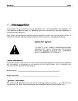
1 - Introduction Congratulations on your choice of a Valmar applicator for your farming operation. This equipment has been designed to meet the needs of a discerning agricultural industry for the pneumatic application of forage preservative products. Safe, efficient and trouble-free operation of your applicator requires that you and all who operate or maintain this machine read and understand all information contained in this Operator's Manual. Safety Alert Symbol This SAFETY ALERT SYMBOL indicates important safety messages in this manual. When you see this symbol be alert to the...
Open the catalog to page 6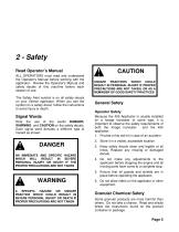
Read Operator’s Manual ALL OPERATORS must read and understand the Operator's Manual before working with the applicator. Review the Operator's Manual and safety decals of this machine before each season of use. The Safety Alert symbol is on all safety decals on your Valmar applicator. When you see the symbol on a safety decal, follow the instructions to avoid injury or death. Signal Words Note the use of the words DANGER, WARNING and CAUTION on the safety decals. Each signal word denotes a different type of hazard as shown: CAUTION UNSAFE PRACTICES WHICH COULD RESULT IN PERSONAL INJURY IF...
Open the catalog to page 7
VALMAR To avoid the possibility of burns, lung damage, or eye irritation: 1. Wear gloves and safety goggles. 2. Avoid contact with skin and eyes. 3. Avoid breathing of dust or fumes. Wear a dust mask or respirator as directed by chemical manufacturer. 4. READ and follow the CHEMICAL MANUFACTURER’S INSTRUCTIONS.
Open the catalog to page 8
Safety Decals Keep safety decals clean and legible at all times. Replace decals that are missing or have become illegible. Safety decals or signs are available from the Valmar parts department. Safety Decal Installation • Be sure installation area is clean and dry. • Decide on the exact position before you remove the backing paper. • Remove the smallest portion of the backing paper. • Align the decal over the specified area and carefully press the small portion of the decal in place. • Small air pockets can be pierced and smoothed out. Safety Decal Locations (Figure 1) All safety decals and...
Open the catalog to page 9
4 - Assembly & Installation Assembly For the most part your 455 Granular Applicator is fully assembled at the factory. The hopper tarp and the control unit are shipped inside the hopper. Open the hopper lid and remove the hopper screen to remove them. Several items remain uninstalled for shipping convenience and are packed in the hopper parts box. Two of these items, the Fan Inlet Screen and the Fan-Manifold Hose, can be installed immediately. The remaining items must be installed after the hopper is installed on the forage harvester or baler. Figure 2 Fan Inlet Screen Installation Install...
Open the catalog to page 11
VALMAR Due to the wide variety of Balers and Silage Choppers on the market, no hopper installation hardware is provided with this applicator as standard equipment. Valmar offers two Installation Kits for round balers. Any additional mounting structures must be fabricated by the purchaser. Hopper Installation (Figure 4) Valmar offers two optional installation kits for installing your 455 Applicator to round balers: Parts Delivery Hose Installation (Figure 5 thru 8) The delivery hose is supplied in a 40 foot coil and must be cut to fit your machine. At the hopper, install the hoses to the...
Open the catalog to page 12
Figure 8 Outlet Tubes Installed Figure 7 Manifold Facing Rear Four outlet tubes are supplied to hold the delivery hoses to their target. They can be held in place using the gear clamp fasteners or threaded fasteners supplied (See Figure 8). Route the delivery hoses from the hopper to the outlet tubes that are directed to the throat of the baler intake. Install the delivery hoses using the following guidelines: 1. Allow ample length for smooth radius curves. Be sure to allow enough hose for all implement positions. 2. Avoid routing hoses into areas where they could be pinched or kinked. 3....
Open the catalog to page 13
VALMAR Parts Delivery Hose Installation (Figure 5) The delivery hose is supplied in a 40 foot coil and must be cut to fit your machine. At the hopper, install the hoses to the venturis by pushing them all the way over the outlet end of the venturi. Note that the manifold containing the venturis can be installed facing to the front or rear of the applicator, see Figure 6 & Figure 7. Choose the configuration that best suits your needs. Route the delivery hoses from the hopper to the forage blower inlet or to the chopper inlet. Four outlet tubes are supplied to hold the delivery hoses to their...
Open the catalog to page 14
feature: either by directly wiring the 455 into an existing mechanism on the baler or harvester, or by installing a lever arm switch. If your round baler, for instance, has an electric tying mechanism, simply connect the green wire on the wiring harness to a wire that provides 12 volts when tying is in progress. When the tying mechanism activates, the control unit will sense the voltage in the green wire and stop the metering of forage preservative. If your baler or harvester has no such electric mechanism, you will need to install the lever arm switch. (Figure 10) To install the switch...
Open the catalog to page 15All Salford Group Inc. catalogs and technical brochures
-
 HALO SERIES
32 Pages
-
 5200 ENFORCER
12 Pages
-
 AerWay
2 Pages
-
 AerWay
16 Pages
-
 AerWay TILLAGE
16 Pages
-
 TILLAGE
16 Pages
-
 VALMAR AIRFLO
28 Pages
-
 AERWAY TILLAGE
16 Pages
-
 INDEPENDENT SERIES
40 Pages
-
 BBI SPREADERS BBI ENDURANCE
36 Pages
-
 VALMAR APPLICATORS
28 Pages
-
 TURF AERATION
8 Pages
-
 1255 TR
69 Pages
-
 ST-10 Granular Applicator
34 Pages
-
 1665
166580 Pages
-
 2055/2455/3255
58 Pages
