
Estratti del catalogo

8.2.3 - REPLACING THE MECHANICAL SEAL - Carry out the disassembly procedure without extracting the pump body; for models type 20 also remove the body (ref. 10), extracting it from the counterflange (ref. 5). - Remove the fixing system of the rotating part of the mechanical seal (this can belong to one of the types in fig. 4). - Extract the rotating part of the seal (ref. 67A Fig. 3a), the counterface (ref. 67B) and the shroud (ref. 67C). - Take an identical seal, separate shroud and counterface, clean the lapped races of the rotating part and of the counterface with a soft cloth; degrease the housing in the pump body and in the shaft, lubricate rubberparts with soap and water. -Insert the shroud into the seat in the pump body, followed by the counterface. - Insert the rotating part of the seal taking care that its rubber parts are not damaged when passing over sharp parts. - Remount the fixing system of the rotating part of the seal; for systems provided with screws, clamp these so that the length of the rotating part is between 13 and 14 mm. 9 - troubleshooting This ohapter is for exclusive use by qualified and expert maintenanoe technicians, operating in compliance with the safety regulations. In particular, during maintenanoe operations the actuation source must be stopped and it must not be possible to start it up Pompa autoadescante a canale laterale Self-priming side channel pump Tipi / Types: CD> MANUALE D’USO E MANUTENZIONE Cgb> user and maintenance manualEd.: 02 Rev.:0 TELLARINI POMPE S.n.c. di G. Tellarini & C. Via E. Majorana, 4 - 48022 LUGO (RAVENNA) - ITALIA Tel. (+39) 0545 22508 - Fax 0545 32362 - E-mail tellarini@tellarini.com24
Aprire il catalogo a pagina 1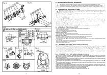
8 - notes for the Service technician The following ehapters 8.1, 8.2, 8.2.1, 8.2.2, 8.2.3 are for thè exclusive use of qualified and expert maintenance technicians, who operate in compliance with the safety regulations. In particular, during maintenance operations the actuation source must be stopped and it must be not be possible to start it l/AL/IFE/ALFE/IFM/ALFM/BS/ALBS X/ALX MIO 10 9 120 8.1 - disassembling the hydraulic part Before disassembly discharge any pressure present inside the pump, wait for it to cool, empty it and dispose of the liquid contained appropriately; if the pump is...
Aprire il catalogo a pagina 2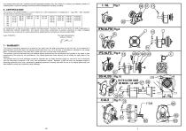
must assess these risks and if necessary provide appropriate protection from jets of liquid (i.e. screens) and collection vessels in a suitable position. Liquid from leakages must be removed and disposed of correctly and safely. 6 - CERTIFICATION The company TELLARINI POMPE s.n.c di G. Tellarini & C. with headquarters in via Majorana, 4 - Lugo (RA) - Italy, classifies the side channel self-priming pumps type: as "components" as they do not have a specific intended purpose. Therefore, they do not fall within the field of application of the Machinery Directive 2006/42/EC. Any person using...
Aprire il catalogo a pagina 3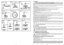
4.4 WASHING Before removing the hoses discharge any pressure present inside the pump. If accessible surfaces are hot (see Chapter 5.1) wait for the pump to cool before handling it or use appropriate gloves. If the pump is used for dangerous substances, the user is responsible for defining the procedures for handling, washing, storing and disposal of waste fluids in compliance with the safety regulations in force for the specific substances treated. If the pumped liquid has no particular problems, (i.e. water, sea water or soap), in the event of an extended period of disuse, wash the inner...
Aprire il catalogo a pagina 4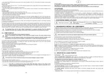
- (only series IFM, ALFM) take the control lever of the clutch to position B (fig. 8); in this position the pulley is disconnected from the pump shaft; series X, ALX - unscrew the breather plug (ref. 94 fig. 11) and fill the speed-up gearbox with oil type SAE 90 to the level indicated by the oil level plug (ref. 95 fig. 11); - mount the protective structures indicated by the designer; - connect the spline shaft of the pump (ref. 60 fig. 11) to the actuation source according to the methods indicated by the designer; series BS, ALBS - insert the shaft of the hydraulic motor in the joint (ref....
Aprire il catalogo a pagina 5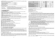
- Temperatura massima: varia in base al tipo di materiale delle guarnizioni (vedere tabella seguente); per i modelli che montano il bypass la temperatura massima di pompaggio è sempre 90°C. Guarnizioni con gomma NBR (montate di serie) Esempi di impiego delle pompe: Table D 3 - DESCRIZIONE TECNICA 3.1 - CARATTERISTICHE La pompa è in grado di aspirare liquido da una bocca (bocca di aspirazione) e inviarlo all'altra bocca (bocca di mandata). Le grandezze in gioco in un problema di pompaggio sono: 1) portata Q: quantità di liquido spostata in un dato tempo; esprime la velocità del pompaggio 2)...
Aprire il catalogo a pagina 6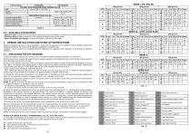
3.5 - AVAILABLE ACCESSORIES - Manual by-pass built into the pump to adjust capacity and head; the relative instructions for use are included in this manual. - Discharge plug or cock, to drain part of the pump body without removing the hoses. - Nylon or stainless steel fittings on request for series in AISI 316 stainless steel. 4 - DESIGN, INSTALLATION AND START-UP INSTRUCTIONS Before the component is used, it must be subjected to design and risk assessment by a qualified technician (designer) following the indications provided in this manual and all regulations applicable to the specific...
Aprire il catalogo a pagina 7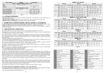
3.5 - ACCESSORI DISPONIBILI - By-pass manuale integrato nella pompa per la regolazione della portata e della prevalenza; le relative istruzioni per l'uso sono incluse in questo manuale - Tappo di scarico / rubinetto di scarico, per svuotare parzialmente il corpo pompante senza rimuovere i tubi - Raccordi in nylon o in acciaio inox su richiesta per le serie in acciaio inox AISI 316. 4 - NORME PER LA PROGETTAZIONE, INSTALLAZIONE E L’AVVIAMENTO L’impiego del componente deve essere preliminarmente oggetto di progettazione e valutazione del rischio ad opera di un tecnico qualificato...
Aprire il catalogo a pagina 8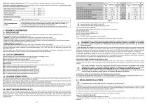
- Must have a minimum temperature of: -15° C, in any case above the freezing temperature of the liquid to be pumped. - Must have a maximum temperature of: varies according to the type of gasket material (see table below); for models with by-pass the maximum pumping temperature is always 90°C. NBR rubber gaskets (mounted standard) 3 - TECHNICAL DESCRIPTION 3.1 - SPECIFICATIONS The pump can perform suction of liquid from one port (suction pori), sending it to the other pori (discharge port); The parameters involved in a pumping problem are: 1) capacity Q: quantity of liquid transferred in a...
Aprire il catalogo a pagina 9


