
Catalog excerpts

OWNER OPERATOR/PARTS MANUAL February 2016 Allen Farm Equipment, LP PO Box 21049 Carson City, NV. 89721 775-246-4555, Fax 775-246-4512 www.AllenFarmEquipment.com
Open the catalog to page 1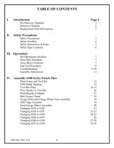
Replacement Parts Information 2 Safety Instructions & Rules 5 Safety Sign Locations 6 Shear Bolt Standards 7 Sway Block Positions 7 IV. Assembly 6300 Series Switch Plow Main Frame and Tool Bar 12 Plow Shanks to Tool Bar 16 Mold Boards to Shanks 17 Bolt Torque Charts 18 Gauge Wheel and Gauge Wheel Arm Assembly 19 Front Gauge Wheel Assembly 20
Open the catalog to page 2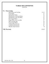
TABLE OF CONTENTS (CONT’D.) VI. Parts Listing Main Frame and Tool Bar 31-32 Mold Boards with Small Slides 35 Mold Boards with Long Slides 35 Rear Gauge Wheel 36 Gauge Wheel Arm Assembly 37 Front Gauge Wheel 39
Open the catalog to page 3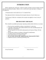
INTRODUCTION Before operating the switch plow, study this manual carefully to become familiar with the operation and safety procedures. Failure to do so could result in personal injury or damage to the equipment. All measurements in this manual are in U.S. Standard Units. The right and left side is determined by facing the direction of travel when in use. The Warranty Certificate is included in this manual and supplied to owner at time of purchase. PRE-DELIVERY CHECKLIST Plow should be assembled and in proper operating condition before delivery to customer. Plow has been assembled...
Open the catalog to page 5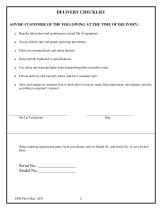
DELIVERY CHECKLIST ADVISE CUSTOMER OF THE FOLLOWING AT THE TIME OF DELIVERY: Regular lubrication and maintenance extend life of equipment. Always follow safe and proper operating procedures. Point out warning decals and safety hazards. Keep all bolts tightened to specifications. Use safety and warning lights when transporting plow on public roads. Fill out delivery and warranty forms, and have customer sign. Show and explain to customer how to hitch plow to tractor, make field adjustment, and operate correctly according to operator’s manual. Set-Up Technician When ordering replacement...
Open the catalog to page 6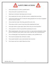
SAFETY PRECAUTIONS Always operate plow in a careful, controlled manner. Always lower plow to ground when not in use. Stand clear of switch plow when being raised or lowered. Never operate plow from side to side while someone is standing inside main frame. All personnel should stand clear of switch plow during preparation for movement of equipment from one location to another. Always stand clear of plow when being operated from side to side. Always place tool bar in center of main frame before unhitching from tractor. Do not park vehicles or place objects within 10 feet of the rear of the...
Open the catalog to page 7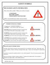
SAFETY SYMBOLS RECOGNIZE SAFETY INFORMATION This is the safety symbol. When you see this, it means: ATTENTION! BECOME ALERT! YOUR SAFETY IS INVOLVED! Follow recommended precautions and procedures. UNDERSTAND SIGNAL WORDS A signal word –DANGER, WARNING, or CAUTION – is used with the safety alert symbol. DANGER indicates imminently hazardous situations that, if not avoided, will result in serious injury, or death. WARNING indicates potentially hazardous situations that, if not avoided, could result in serious injury, or death. WARNING may also be used to alert against unsafe practices....
Open the catalog to page 8
KEEP RIDERS OFF MACHINE Only allow the operator on the machine. Keep riders off. Riders on machine are subject to injury such as being struck by foreign objects and being thrown off the machine. Riders also obstruct the operator’s view resulting in the ^ machine being operated in an unsafe manner. OPERATOR’S MANUAL Do not put this operator’s manual away unread. Read the manual carefully regardless of previous experience. Allow yourself this time, it will save time and labor later on. IMPORTANT: Keep an extra copy of the operator’s manual in your office or in the garage in case one gets...
Open the catalog to page 9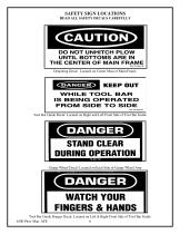
SAFETY SIGN LOCATIONS READ ALL SAFETY DECALS CAREFULLY Detaching Decal: Located on Center Mast of Main Frame. Tool Bar Guide Decal: Located on Right and Left Front Side of Tool Bar Guide . Gauge Wheel Decal: Located on Each Side of Gauge Wheel Arm Tool Bar Guide Danger Decal: Located on Left & Right Front Side of Tool Bar Guide 6300 Plow Man. AFE 6
Open the catalog to page 10
OPERATIONS PRE-OPERATIONS CHECKLIST All tractor preparation should be as recommended in your Tractor Operator’s Manual. Tractor should be fully weighted in accordance with Tractor Manufacturer’s recommendations. 1. Tractor has been prepared according to Tractor Operator’s Manual and Start-Up Procedures on page 8. 2. Tractor Sway Blocks are in position as recommended in section on “Sway Block Positions”. 3. The Plow has been prepared and properly attached to tractor and is operating as designed. 4. Adjust both lift links on tractor to same length. 5. Grease main tool bar pivot pin (every 8...
Open the catalog to page 11
STARTUP PROCEDURES IMPORTANT! MAKE SURE CYLINDER IS ADJUSTED PROPERLY SO THAT BEAM TOUCHES BOTH SIDES OF FRAME, OTHERWISE, IT COULD DAMAGE CYLINDER. All tractor preparations should be as recommended in your Tractor Operator’s Manual. Tractor should be fully weighted in accordance with Tractor Manufacturer’s recommendations. 1. Make sure rear end side duals have water in them. 2. Full set of weights on front of tractor. 3. Make sure the lift arms on the tractor are extended out at least 3 to 4 inches otherwise, front plows will not take the ground. If necessary, extend out more. For on land...
Open the catalog to page 12
ASSEMBLY INTRUCTIONS 6300 SERIES SWITCH PLOW MAIN FRAME AND TOOL BAR (REFER TO FIGURE 2) CAUTION: The Main Frame should be supported by adequate floor supports that will support the weight of the frame and any added plow components Es necesario soportar el armazon principal suficientemente para soportar las armazon tambien con el pest de las otras adiciones del arado. Remove the tool bar pivot pin from the main frame and clean paint from both the pivot pin and pivot hole. Apply a good layer of grease to the pivot pin and pivot hole through main frame. Insert the tool bar into the main frame...
Open the catalog to page 15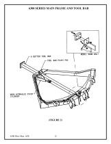
6300 SERIES MAIN FRAME AND TOOL BAR
Open the catalog to page 16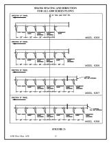
SHANK SPACING AND DIRECTION FOR ALL 6300 SERIES PLOWS
Open the catalog to page 17All Allen Farm Equipment catalogs and technical brochures
-
MODEL 8794
52 Pages
-
MODEL 8200
49 Pages
-
MODEL 8803
101 Pages
-
MODEL 8603
45 Pages


