
Catalog excerpts

BRAVO 400S LT SERIES COMPUTER MULTI-ROW SPRAYER
Open the catalog to page 1
LEGEND OF SYMBOLS = Generic danger This manual is an integral part of the equipment to which it refers and must accompany the equipment in case of sale or change of ownership. Keep it for any future reference; ARAG reserves the right to modify product specifications and instructions at any moment and without notice.
Open the catalog to page 2
MANUAL USE MODES The section of this manual dedicated to the installation contains information for installers. For this reason we have used technical terms without providing any explanations. THE INSTALLATION MUST BE CARRIED OUT BY AUTHORISED AND SKILLED PERSONNEL ONLY. THE MANUFACTURER IS NOT RESPONSIBLE FOR ANY OPERATION SPECIFIED IN THIS MANUAL CARRIED OUT BY UNAUTHORISED OR UNSKILLED PERSONNEL. • RESPONSIBILITY The installer must carry out workmanlike installations and ensure to the end user the perfect operation of the whole system both with ARAG components only and other brands'...
Open the catalog to page 5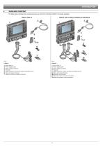
PACKAGE CONTENT The table below indicates the components that you will find in the Bravo 400S LT computer package: BRAVO 400S LT BRAVO 400S LT WITH HYDRAULIC CONTROLS 1 Bravo 400S LT 2 Power supply cable 3 Power supply connector 4 Fixing kit 5 Safety covers for control unit valve connectors (no. 2) 6 Valve and sensor harness 7 Seals for control unit valve connectors 1 Bravo 400S LT 2 Power supply cable 3 Power supply connector 4 Fixing kit 5 Safety covers for control unit valve connectors (no. 2) 6a Valve and sensor harness 6b Hydraulic unit harness 7a Seals for control unit valve...
Open the catalog to page 6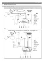
POSITION ON FARMING MACHINE System recommended composition ASSEMBLY DIAGRAM FOR MULTI-ROW SPRAYER WITH DIAPHRAGM PUMP - SYSTEM WITH MAIN VALVE Legend: A Monitor B Battery C GPS receiver D Filling pump E Oil-hydraulic unit F Flowmeter G Main valve H External main control M Pressure sensor P Regulating valve S Speed sensor T Filling flowmeter / Level sensor V1 Camera 1 V2 Camera 2 X RPM sensor 1-7 Section valves Fig. 3 ASSEMBLY DIAGRAM FOR MULTI-ROW SPRAYER WITH CENTRIFUGAL PUMP - SYSTEM WITH MAIN VALVE Legend: A Monitor B Battery C GPS receiver D Filling pump E Oil-hydraulic unit F Flowmeter...
Open the catalog to page 7
Computer positioning • The Bravo 400S LT series computer must be placed in the control cabin of the farming machine. Observe the following precautions: - Do NOT install the computer in areas where it would be subjected to excessive vibrations or shocks, to prevent any damage or accidental use of the control keys; - Install the device in a visible position within easy reach by hand; bear in mind that the computer should not obstruct the operator’s freedom of movement or block his/her view. Consider all necessary connections of the computer (Fig. 5), the cable length, and make sure there is...
Open the catalog to page 8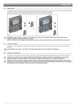
Bracket fixing The computer must be mounted after having fixed the bracket at the desired location (the previous paragraph shows the bracket drilling template). The bracket must be slid out of the computer seat (A, Fig. 6) and fixed using the supplied screws (B). Make sure the bracket is securely mounted, fit the computer on it, and push it until it locks in place (C). WARNING: the Bravo 400S LT computer must be fastened by means of the supplied bracket only, using suitable screws. OTHER FASTENING METHODS ARE NOT ALLOWED. ARAG is not liable for any damage to the equipment, persons or...
Open the catalog to page 9
WIRING CONNECTIONS WARNING: To avoid short circuits, do not connect the power cables to battery before the installation is completed. Before powering up the computer, make sure the tractor battery voltage is as specified (12 VDC). • Only use ARAG harnesses suitable for Bravo 400S LT computer. • Take care not to break, pull, tear or cut the cables. • Use of unsuitable cables not provided by ARAG automatically voids the warranty. • ARAG is not liable for any damage to the equipment, persons or animals caused by failure to observe the above instructions. General precautions for a correct...
Open the catalog to page 10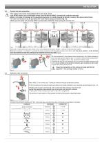
Control unit valve connection • The system only works if assembled with 3-wire type valves. • Use ARAG valves: use of unsuitable valves not provided by ARAG automatically voids the warranty. ARAG is not liable for damage to the equipment, persons or animals caused by failure to observe the above instructions. • All valve connectors must be provided with seals before being connected (Fig. 10). • Make sure the seals are correctly fitted to avoid water infiltration when using the control unit. Valve 1 Connector 1 shall control the valve, which in turn is connected to the boom section 1, and so...
Open the catalog to page 11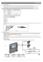
Sensor connection Fix the connectors to the relevant functions according to the initials indicated in your assembly general diagram (par. 5.1). Harness cables are marked with a symbol denoting their functions: please see the table for correct harness connection. Use ARAG sensors: use of unsuitable sensors not provided by ARAG automatically voids the warranty. ARAG is not liable for damage to the equipment, persons or animals caused by failure to observe the above instructions. ITEM MAIN CONNECTION ALTERNATIVE CONNECTION Pressure sensor Speed sensor Filling flowmeter Level sensor - The...
Open the catalog to page 12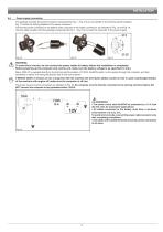
Power supply connection The package includes the power connector (component 5, Fig. 1 / Fig. 2) to be connected to the farming machine battery; Fig. 17 shows the drilling template of the power connector. Connect the power connector to the battery wires using two 6-mm faston connectors, as indicated in Fig. 15 and Fig. 16. Use the cable provided with the package (component 3, Fig. 1 / Fig. 2) to connect the computer to the power supply. WARNING: To avoid short circuits, do not connect the power cables to battery before the installation is completed. Before powering up the computer and...
Open the catalog to page 13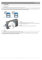
SD memory card The SD memory card may be used to exchange data with the Bravo 400S LT computer. Before use, format the SD card in FAT 32 mode; make sure that the card is not protected and can be read by the system (Fig. 19). The system is ONLY compatible with SD or SDHC memory cards with up to 8 Gb memory. • Insertion Insert the memory card making sure to orient it correctly: the card cut edge A must be face down; push the card until it engages into place and close the slot with the cover. • Removal Press and immediately release the card into the slot and slide it out. Pendrive The pendrive...
Open the catalog to page 14All ARAG S.r.l. catalogs and technical brochures
-
 ibX20
ibX2016 Pages
-
 ISOBUS
20 Pages
-
 Arag 2020
24 Pages
-
 C111a General Catalogue 2017
548 Pages


