
Catalog excerpts
= Generic danger = Warning ECU = IBX20 remote control unit VT WARNING: T H E N AT I V E C O N T R O L S I N S I D E Y O U R V I R T U A L TERMINAL HAVE THE PRIORITY ON ALL THE CONTROLS DERIVING FROM THE IBX20. PLEASE, KEEP THIS IN MIND WHEN PROGRAMMING AND USING THE PRODUCT. This manual is an integral part of the equipment to which it refers and must accompany the equipment in case of sale or change of ownership. Keep it for any future reference; ARAG reserves the right to modify product specifications and instructions at any moment and without notice.
Open the catalog to page 2
MANUAL FOREWORD AND USE The section of this manual dedicated to the installation contains information for installers. For this reason we have used technical terms without providing explanations which would be necessary for end users only. THE INSTALLATION MUST BE PERFORMED BY AUTHORIZED AND SPECIFICALLY TRAINED PERSONNEL. ARAG IS NOT RESPONSIBLE FOR ANY INSTALLATION CARRIED OUT BY UNAUTHORIZED OR UNSKILLED PERSONNEL. RESTRICTIONS The descriptions of the assembly phases refer to a "general" Virtual Terminal, so specific models will not be mentioned, unless a certain installation procedure...
Open the catalog to page 4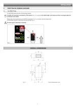
POSITION ON FARMING MACHINE Tecu IBX20 Fixing Fix the IBX20 inside the cabin of the farming machine. Consider all necessary connections of the device (par. 5.2 on page 6), the cable length, and make sure there is enough space for connectors and cables. Respect the mounting direction of the IBX20, as specified in Fig. 2 (connector shall be facing down). Fix the IBX20 using the 3 bolts fitted into their slots (A, Fig. 2). No other type of assembly is allowed. OVERALL DIMENSIONS
Open the catalog to page 5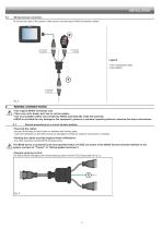
Wiring harness connection To connect all parts of the system, make sure to use the proper ARAG connection cables. Legend: 1 Tecu connection cable 2 Tecu IBX20 WIRING CONNECTIONS • Use original ARAG harnesses only. • Take care not to break, pull, tear or cut the cables. • Use of unsuitable cables not provided by ARAG automatically voids the warranty. • ARAG is not liable for any damage to the equipment, persons or animals caused by failure to observe the above instructions. 6.1 General precautions for a correct harness position - secure the harness so that it does not interfere with moving...
Open the catalog to page 6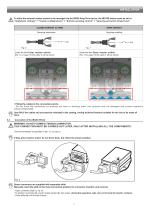
To allow the external master control to be managed via the IBX20 Arag Tecu device, the IBX100 Isobus must be set to: “Implement settings” > “System configurations” > “Remote spraying control” > “Spraying activation (Arag-Tecu)”. CLOSED CONTACT (to GND) OPEN CONTACT Spraying interruption Spraying enabling Under the item Exter. master switch (Fig. 14 on page 10) the value 1 will be shown. Under the item Exter. master switch (Fig. 14 on page 10) the value 0 will be shown. • Fitting the cables to the connection points: - Do not force the connectors by pushing too hard or bending them: the...
Open the catalog to page 7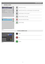
CONTROL LAYOUT Goes back to main screen Goes back to previous menu, or scrolls the pages of a menu (previous page) Scrolls the pages of a menu (next page) Saves the changes to current page Fig. 9 Quits without confirming the changes Fig. 10 ENTERING A NUMERICAL VALUE
Open the catalog to page 8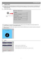
"OBJECT POOL" Images and the relevant description texts contained in this manual are given as a reference as they can vary depending on the Virtual Terminal used. If the descriptions do not correspond to the text displayed in your Virtual Terminal, refer to the manual attached to the latter. "OBJECT POOL" loading Press to enter the main screen. The IBX20 device is powered by the key-operated switch (+15/54), by means of the ARAG harness already installed on the system (version for "Tractor" or "Self-propelled machines"). When the key-operated switch power supply is turned off (+15/54), the...
Open the catalog to page 9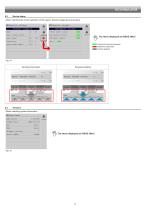
Device status Allows checking the correct operation of the system. Several categories are grouped. The items displayed are READ ONLY. Properly functioning hardware. Hardware malfunction Control disabled Spraying enabling Allows checking system information. The items displayed are READ ONLY.
Open the catalog to page 10
Speed settings This menu defines the source of the input speed to the IBX20 and how it should be distributed on the ISOBUS bus, to the IBX100. 1 1 2 3 Frequency input: Allows enabling an external source that provides pulse/frequency as the speed Simulated speed: allows enabling speed simulation in order to carry out adjustment tests even when 2 Wheel sensor constant: Enter the wheel constant value by manually calculating it with the suitable formula. The wheel constant can be calculated with a good approximation by detecting the distance traveled by the wheel with the speed sensor. The...
Open the catalog to page 11
Access level • Operator: inhibits any kind of setting. • Manager: inhibits speed setting but allows configuration of the speed source. You can set an access PIN code. • Technician: allows configuring the parameters of the Speed settings (8.5 on page 11) menu. You can set an access PIN code. • ARAG Tech: for ARAG staff, only. This menu allows entering the ECU registration code. 1 Press and enter the code, then confirm. 1
Open the catalog to page 12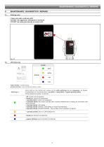
MAINTENANCE / DIAGNOSTICS / REPAIRS 9 MAINTENANCE / DIAGNOSTICS / REPAIRS Cleaning rules - Clean only with a soft wet cloth. - DO NOT use aggressive detergents or products. - DO NOT aim water jets directly at control unit. LED status key COLOR green yellow - regular blinking = constant blinking - periodical blinking = series of blinks interrupted by a pause Upon start-up, the control unit carries out the LED switching on in a sequence, as follows: If connected to VT for the first time: 1 red blink - 2 blue blinks - 3 green periodic blinks Whole sequence duration: 2 seconds - off: control...
Open the catalog to page 13
Alarms detail The IBX20 detects a second Tractor radar (PGN65096) signal on the ISOBUS bus. The IBX20 detects a second Tractor wheel (PGN65097) signal on the ISOBUS bus.
Open the catalog to page 14
TECHNICAL DATA DESCRIPTION Power supply voltage Operating temperature Storage temperature Weight (without cables) Digital inputs Protection against polarity inversion Protection against short-circuit Protection rating 100 g For Open Collector sensors: max frequency 2000 Hz • • IPX4 END-OF-LIFE DISPOSAL Dispose of the system in compliance with the established legislation in the country of use. GUARANTEE TERMS 1. ARAG s.r.l. guarantees this apparatus for a period of 360 days (1 year) from the date of sale to the client user (date of the goods delivery note). The components of the apparatus,...
Open the catalog to page 15All ARAG S.r.l. catalogs and technical brochures
-
 ISOBUS
20 Pages
-
 Arag 2020
24 Pages
-
 C111a General Catalogue 2017
548 Pages


