D-020
1 /4Pages

D-020
1 /4Pages
Catalog excerpts
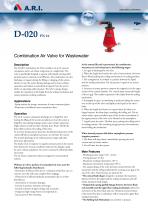
Combination Air Valve for Wastewater Description The D-020 Combination Air Valve combines an air & vacuum component and an air release component in a single body. The valve is specifically designed to operate with liquids carrying solid particles such as wastewater and effluents. The combination air valve discharges air (gases) during the filling or charging of the system, admits air into the system during drainage and at water column separation and releases accumulated air (gases) from the system while it is operating under pressure. The valve’s unique design enables the separation of the liquid from the sealing mechanism and assures optimum working conditions. -Pump stations for sewage, wastewater & water treatment plants. -Wastewater and effluent water transmission lines. The air & vacuum component discharges air at high flow rates during the filling of the system and admits air into the system at high flow rates during drainage and at water column separation. High velocity air will not blow the float shut. Water will lift the float which activates the sealing of the valve. At any time during system operation, should internal pressure of the system fall below atmospheric pressure, air will enter the system. The smooth discharge of air reduces pressure surges and other destructive phenomena. The intake of air in response to negative pressure protects the system from destructive vacuum conditions and prevents damage caused by water column separation. Air entry is essential to efficiently drain the system. The air release component releases entrapped air in pressurized systems. Without air valves, pockets of accumulated air may cause the following hydraulic disturbances: - Restriction of effective flow due to a reduction of the flow area. In extreme cases this will cause complete flow stoppage. - Obstruction of efficient hydraulic transmission due to air flow disturbances. - Acceleration of cavitation damages. - Increase in pressure transients and surges. - Internal corrosion of pipes, fittings and accessories. - Dangerous high-energy bursts of compressed air. - Inaccuracies in flow metering. As the system fills and is pressurized, the combination wastewater air valve functions in the following stages: 1. Air (gas) is discharged by the valve. 2. When the liquid level reaches the valve’s lower portion, the lower float is lifted, pushing the sealing mechanism to its sealing position. 3. The entrapped air is confined in a pocket between the liquid and the sealing mechanism. The air pressure is equal to the system pressure. 4. Increases in system pressure compress the trapped air in the upper section of the conical chamber. The conical shape assures the height of the air gap. This enables separation of the liquid from the sealing mechanism. 5. Entrapped air (gas), accumulating at peaks and along the system, rises to the top of the valve and displaces the liquid in the valve’s body. 6. When the liquid level lowers to a point where the float is no longer buoyant, the float drops, unsealing the rolling seal. The air release orifice opens and allows part of the air that accumulated in the upper portion of the valve to be released to the atmosphere. 7. Liquid enters the valve. The float rises, pushing the rolling seal to its sealing position. The remaining air gap prevents the wastewater from fouling the mechanism. When internal pressure falls below atmospheric pressure (negative pressure): 1. The floats will drop down, immediately opening the air & vacuum and air release orifices. 2. Air will enter into the system. Main Features - Working pressure range: 0.05 - 16 bar. - Testing pressure: 25 bar. - Maximum working temperature: 60° C. - Maximum intermittent temperature: 90° C. - The unique design of the valve prevents contact between the wastewater and the sealing mechanism by creating an air gap at the top of the valve. These features are achieved by: • The conical body shape: designed to maintain the maximum distance between the liquid and the sealing mechanism and still obtain minimum body length. • Independent spring-guided linkage between the lower float/ rod assembly and the upper float sealing mechanism: allows free movement of the lower float and rod. Vibrations and movement of the lower float due to turbulence will not unseal the upper float sealing mechanism. • The Rolling Seal Mechanism: less sensitive
Open the catalog to page 1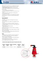
differentials than a direct float seal. It accomplishes this by having a comparably large orifice for a wide pressure range (up to 16 bar). • Funnel-shaped lower body: designed to ensure that residue wastewater matter will fall back into the system and be carried away by the main pipe. - All inner metal parts made of stainless steel. - U/2" threaded discharge outlet enables for the connection of a vent hose/pipe. - Dynamic design allows for high capacity air discharge while preventing premature closure. - The ball valve can be opened to release trapped pressure and drain the valve body prior...
Open the catalog to page 2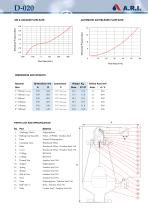
AIR & VACUUM FLOW RATE AUTOMATIC AIR RELEASE FLOW RATE Flow Rate [m3/h] Orifice Area mm2 Auto. A / V 12 804 PARTS LIST AND SPECIFICATION No Part_ Material Polypropylene Nylon + EPDM + Stainless Steel Foamed Polypropylene Reinforced Nylon Reinforced Nylon / Stainless Steel 316 Reinforced Nylon / Stainless Steel 316 BUNA-N BUNA-N Stainless Steel 304 Polypropylene Stainless Steel 316 Stainless Steel 316 Stainless Steel 316 Stainless Steel 316 Polypropylene / Stainless Steel 316 Brass / Stainless Steel 316 Carbon Steel / Stainless Steel 316
Open the catalog to page 3
A.R.I. FLOW CONTROL ACCESSORIES Ltd. www.arivalves.com [email protected] Tel: 972-4-6761988 A.R.I. FLOW CONTROL ACCESSORIES Ltd. reserves the right to make product changes without prior notice. To insure receiving updated information on parts specifications, please call the export dept. at the A.R.I. factory. A.R.I. FLOW CONTROL ACCESSORIES Ltd. shall not be held liable for any errors. All rights reserved.
Open the catalog to page 4All Arivalves catalogs and technical brochures
 VB-060
4 Pages
 S-021
S-0212 Pages
 S-020 - S-022
4 Pages
 D-025-SB
4 Pages
 D-43
D-436 Pages
 SG-10, S-050
2 Pages
 NR-040
2 Pages
 DC-500
2 Pages
 D-021
D-0212 Pages
 R-20
R-204 Pages
