D-021
1 /2Pages

D-021
1 /2Pages
Catalog excerpts

Reclaimed Water Combination Air Valve - Reclaimed and Non-Potable Water Description The D-021 Combination Air Valve combines an air & vacuum orifice and an air release orifice in a single body. The valve is specially designed to operate with liquids carrying solid particles such as reclaimed water and effluents. The combination air valve discharges air (gases) during the filling or charging of the system, admits air into the system while it is being emptied of liquid and releases accumulated air (gases) from the system while it is under pressure and operating. The valve’s unique design enables the separation of the liquid from the sealing mechanism and assures optimum working conditions. - Reclaimed water - Raw water - Effluent water - Water with suspended solids - Coolant water The air & vacuum component discharges air at high flow rates during the filling of the system and admits air into the system at high flow rates during its drainage and at water column separation. High velocity air will not blow the float shut. Water will lift the float which seals the valve. At any time during system operation, should internal pressure of the system fall below atmospheric pressure, air will enter the system. The smooth discharge of air reduces pressure surges and other destructive phenomena. The intake of air in response to negative pressure protects the system from destructive vacuum conditions and prevents damage caused by water column separation. Air entry is essential to efficiently drain the system. The automatic air release component releases entrapped air in pressurized systems. Without air valves, pockets of accumulated air may cause the following hydraulic disturbances: - Restriction of effective flow due to a throttling effect as would a partially closed valve. In extreme cases this will cause complete flow stoppage. - Obstruction of efficient hydraulic transmission due to air flow disturbances. - Accelerate cavitation damages. - Pressure transients and surges. Corrosion in pipes, fittings and accessories. - Danger of high-energy bursts of compressed air. - Inaccuracies in flow metering. As the system starts to fill, the combination wastewater valve functions according to the following stages: 1. Entrapped air/gas is discharged by the valve. 2. When the liquid level reaches the valve’s lower portion, the lower float is lifted, pushing the sealing mechanism to its sealing position. 3. The entrapped air is confined in a pocket between the liquid and the sealing mechanism. The air pressure is equal to the system pressure. 4. Increases in system pressure compress the trapped air in the upper section of the conical chamber. The conical shape assures the height of the air gap. This enables separation of the liquid from the sealing mechanism. 5. Entrapped air (gas), accumulating at peaks and along the system, rises to the top of the valve, and displaces the liquid in the valve’s body. 6. When the liquid level is lowered to a point where the float is no longer buoyant, the float drops, unsealing the rolling seal. The air release orifice opens and allows part of the air that accumulated in the upper portion of the valve to be released to the atmosphere. 7. Liquid enters the valve. The float rises, pushing the rolling seal to its sealing position. The remaining air gap prevents the wastewater from fouling the mechanism. When internal pressure falls below atmospheric pressure (negative pressure): 1. The floats will immediately drop down, opening the air & vacuum and air release orifices. 2. Air enters into the system. Main Features - Working pressure range: 0.2 - 10 bar Testing pressure: 16 bar - Maximum working temperature: 60° C. - Maximum intermittent temperature: 90° C. - The unique design of the valve prevents contact between the wastewater and the sealing mechanism by creating an air gap at the top of the valve. These features are achieved by: • The conical body shape: designed to maintain the maximum distance between the liquid and the sealing mechanism and still obtain minimum body length. • Spring-loaded joint between the stem and the upper float: vibrations of the lower float will not unseal the air release component. Release of air will occur only after enough a
Open the catalog to page 1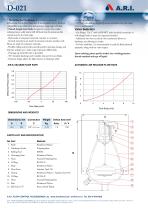
4\ A.R.I • The Rolling Seal Mechanism: less sensitive to pressure differentials than a direct float seal. It accomplishes this by having a comparably large orifice for a wide pressure range (up to 10 bar). • Funnel-shaped lower body: designed to ensure that residue reclaimed water solid matter will fall back into the system and be carried away by the main pipe. - Body made of composite materials, resistant to corrosion. - Internal metal parts are made of corrosion-resistant stainless steel. Floats are made of composite materials. - Flexible rolling seal provides smooth positive opening, closing,...
Open the catalog to page 2All Arivalves catalogs and technical brochures
 VB-060
4 Pages
 S-021
S-0212 Pages
 S-020 - S-022
4 Pages
 D-025-SB
4 Pages
 D-43
D-436 Pages
 D-020
D-0204 Pages
 SG-10, S-050
2 Pages
 NR-040
2 Pages
 DC-500
2 Pages
 R-20
R-204 Pages
