D-025-SB
1 /4Pages

D-025-SB
1 /4Pages
Catalog excerpts
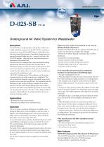
Underground Air Valve System for Wastewater Description The D-025 SB is a complete product package that combines the reliable and efficient properties of the A.R.I. D-025 combination wastewater air valve with the added feature of a sub-surface valve that can be buried below ground. A specifically designed gear box operated horizontal sliding disc valve - situated at the base of the D-025 SB assembly - allows for the air valve disconnection and maintenance from ground level. This shut-off valve is equipped with a safety mechanism enabling disconnection and removal of the D-025 air valve from its subsurface housing, even when the system is under pressure. Since service and maintenance operations of the unit are performed entirely from the surface, there is no need for safety considerations associated with confined space entry. The D-025 Combination Air Valve combines an air & vacuum component and an air release component in a single body. The valve is specifically designed to operate with liquids carrying solid particles such as wastewater and effluents. The combination air valve discharges air (gas) during the filling or charging of the system, admits air into the system during drainage and at water column separation and releases accumulated air (gas) from the system while it is operating under pressure. The valve’s unique design enables the separation of the liquid from the sealing mechanism and assures optimum working conditions. - Wastewater & water treatment plants. - Wastewater and effluent water transmission lines. The air & vacuum component discharges air at high flow rates during the filling of the system and admits air into the system at high flow rates during drainage and at water column separation. High velocity air will not blow the float shut. Water will lift the float which activates the sealing of the valve. At any time during system operation, should internal pressure of the system fall below atmospheric pressure, air will enter the system. The smooth discharge of air reduces pressure surges and other destructive phenomena. The intake of air in response to negative pressure protects the system from destructive vacuum conditions and prevents damage caused by water column separation. Air entry is essential to efficiently drain the system. The air release component releases entrapped air in pressurized systems. Without air valves, pockets of accumulated air may cause the following hydraulic disturbances: - Restriction of effective flow due to a reduction of the flow area. In extreme cases this will cause complete flow stoppage. - Obstruction of efficient hydraulic transmission due to air flow disturbances. - Acceleration of cavitation damages. - Increase in pressure transients and surges. - Internal corrosion of pipes, fittings and accessories. - Dangerous high-energy bursts of compressed air. - Inaccuracies in flow metering. As the system fills and is pressurized, the combination wastewater air valve functions in the following stages: 1. Air (gas) is discharged by the valve. 2. When the liquid level reaches the valve’s lower portion, the lower float is lifted, pushing the sealing mechanism to its sealing position. 3. The entrapped air is confined in a pocket between the liquid and the sealing mechanism. The air pressure is equal to the system pressure. 4. Increases in system pressure compress the trapped air in the upper section of the conical chamber. The conical shape assures the height of the air gap. This enables separation of the liquid from the sealing mechanism. 5. Entrapped air (gas), accumulating at peaks and along the system, rises to the top of the valve and displaces the liquid in the valve’s body. 6. When the liquid level lowers to a point where the float is no longer buoyant, the float drops, unsealing the rolling seal. The air release orifice opens and allows part of the air that accumulated in the upper portion of the valve to be released to the atmosphere. 7. Liquid enters the valve. The float rises, pushing the rolling seal to its sealing position. The remaining air gap prevents the wastewater from fouling the mechanism. When internal pressure falls below atmospheric pressure (negative pressure): 1. The floats will drop down, immediately opening the air & vacuum and air release orifices. 2. Air will enter into the system. Main Features D-025 SB Underground Air Valve System for Wastewater: - The D-025 SB incorporates an integral, flat, gear box operated horizontal sliding disc valve with a 3” full bore passage. - The shut-off valve is operated from the sur
Open the catalog to page 1
- Easy and efficient back flushing can be achieved while the air valve is in its sub-surface housing. - All connections utilize quick connectors to facilitate easy usage during: 1. Handling (quick connector from adaptor to shut-off valve) 2. Maintenance operations (quick connectors on both the inlet & outlet flushing positions). -Safety elements: Disengaging the air valve is safeguarded: unless the shut-off valve is in the “closed” position and the internal pressure is released, it is not possible to extract the air valve. - Pipe connections: 3” threaded (BSP/NPT) or flanged, in accordance with...
Open the catalog to page 2
UNDERGROUND AIR VALVE SYSTEM PARTS LIST AND SPECIFICATION 4. Pressure Relief Valve 5. Lifting Handle 6. Back Flushing Assembly 7. Operating Rod 9. Sliding Disc Valve w/ Gear Box Polypropylene Polyethylene Stainless Steel 304 Stainless Steel 316 Stainless Steel 304 Polyethylene Stainless Steel 304 see below DI+STST+EPDM /STST + STST + EPDM 10. Adaptor - Quick Connector 3 11. Safety Handle 12. “T” Key Stainless Steel 316 Stainless Steel 316 Stainless Steel 304 Polyethylene Reinforced Nylon /Stainless Steel 316 D-025 PARTS LIST AND SPECIFICATION Polypropylene Reinforced Nylon + EPDM...
Open the catalog to page 3
D-025-SB AIR & VACUUM FLOW RATE Flow Rate [m3/h] AUTOMATIC AIR RELEASE FLOW RATE 10 Important Information: Prior to site preparation and installation, please refer to the D-025 SB Installation and Maintenance Manual for all the relevant instructions and information. The manual can be obtained by contacting the A.R.I marketing dept., from your local A.R.I. distributor or downloading the file from our website. DIMENSIONS AND WEIGHTS Model A.R.I. FLOW CONTROL ACCESSORIES Ltd. www.arivalves.com [email protected] Tel: 972-4-6761988 A.R.I. FLOW CONTROL ACCESSORIES Ltd. reserves the right to make product...
Open the catalog to page 4All Arivalves catalogs and technical brochures
 VB-060
4 Pages
 S-021
S-0212 Pages
 S-020 - S-022
4 Pages
 D-43
D-436 Pages
 D-020
D-0204 Pages
 SG-10, S-050
2 Pages
 NR-040
2 Pages
 DC-500
2 Pages
 D-021
D-0212 Pages
 R-20
R-204 Pages
