
- Catalogs
- Assentoft Silo
- S 1000

S 1000
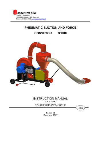
S 1000
The manual for the Pneumatic Suction and Force Conveyor S 1000 is crucial for safe operation and must be read by all users and service personnel. Identification details are found on the data plate attached to the conveyor.
Key safety instructions include reading the manual thoroughly, ensuring only informed adults operate the machine, maintaining the machine in good condition, following safety precautions, using original spare parts, and regularly checking components.
Safety signs on the conveyor must be kept clean and legible, with damaged or missing labels replaced.
The S 1000 is designed for transporting grains and seeds, suitable for family farms and warehouses, but not for constant work. It operates in suction and force or force-only modes.
Specifications include a max transportation length of 40m, height of 10m, pipe diameter of 160mm, radial fan type, 7.5 kW electric engine power, and a noise level of 94 dB.
The conveyor includes units like a fan, framework, feeder, and cyclone. In suction and force mode, grain is sucked in, separated from air in the cyclone, and transported through the pipeline.
The conveyor features protective grounding, rated IP-54, with a star-delta switch and engine switch with undervoltage trip.
Regular maintenance is essential for safe operation, with electrical repairs only by authorized personnel.
Guidelines are provided for troubleshooting common issues.
Instructions for preserving and safely dismantling the machine are included.
The warranty is void if the machine is improperly used, modified without consent, or if non-original parts are used.
Details on the electrical installation include trip range adjustment, supply plug specifications, and connecting cord details. Electric engines are protected by trips with thermal and short-circuit releases.
A diagram details components like the electric engine of the fan’s drive, engine switch with undervoltage trip, and star-delta switch.
The conveyor should be placed on a horizontal surface, requires a 3x400V power supply, and protection by 20A fuses. An authorized electrician should verify the earthing system.
Instructions for starting and stopping engines include using the star-delta switch and master switch, with the first start-up supervised by an authorized electrician.
The valve regulates airflow to prevent engine overload and maintain airflow speed.
Guidelines include using the suction nozzle correctly and maintaining the right air-to-grain ratio.
Safety precautions include not operating the machine without supervision and ensuring proper earthing. Maintenance involves checking for vibrations or unusual sounds.
The system should be mounted as per the diagram, allowing for higher performance and transporting small seeds without damaging the fan.
Regular maintenance includes daily checks and periodical inspections every 100 and 500 hours.
Common issues include master switch problems and grain blockages, with solutions involving adjusting valves and cleaning components.
Post-season, the conveyor should be cleaned and stored in a dry area, with electrical systems protected from moisture.
Metal parts should be recycled, while rubber and plastic elements should be taken to a utilization center.
The conveyor is available in suction and force versions, with specific components included.
Residual risks arise from improper use or maintenance, mitigated by following the manual and safety guidelines.
Spare parts can be ordered from the producer or authorized sellers.
A detailed list of components for the suction unit and electrical system is provided.
The warranty covers defects due to the producer's fault for twelve months from purchase, with specific responsibilities for the producer and buyer.
The warranty covers defects from defective material or assembly, excluding normal wear and tear.
Claim vouchers require product details and are forwarded with the claim report to the producer.
Catalog excerpts

Silovej 1, Assentoft DK-8960 Randers SØ, Denmark Phone +45 86494566, www.assentoftsilo.dk PNEUMATIC SUCTION AND FORCE CONVEYOR INSTRUCTION MANUAL (ORIGINAL) SPARE PARTS CATALOGUE Eng Edition III Denmark, 2007
Open the catalog to page 1
PNEUMATIC SUCTION AND FORCE CONVEYOR S 1000 (DIAMETER OF PIPELINE 160 mm) INSTRUCTION MANUAL SPARE PARTS CATALOGUE Serial number ……………. Year of production …………….
Open the catalog to page 3
2. WARNING AND INFORMATION GRAPHICS 8. WORK WITH THE CONVEYOR 9. WORK IN SUCTION AND FORCE SYSTEM 10. WORK IN FORCE SYSTEM 14. DISMANTLING AND DEMOLITION INSTRUCTIONS 15. STANDARD OUTFIT FOR SALE, TRANSPORT 16. RESIDUAL RISK DESCRIPTION SPARE PARTS CATALOGUE WARRANTY CONDITIONS
Open the catalog to page 4
INTRODUCTION Instruction manual belongs to the standard outfit of the machine. In case the machine is sold again, this instruction manual must be given to the end-user. This instruction manual must be read and followed by all personnel using, setting up or servicing the machine. Following the guidelines included into the present manual will guarantee nonfailure work and effective use of the machine. Identification details can be found on data plate attached to the conveyor’s framework. In case of any doubts or incomprehension of text herein, contact the producer of the machine, i.e.: ATTENTION...
Open the catalog to page 5
ATTENTION ! 1. When operating the machine in a humid room or area always use watertight cables, plugs and sockets which enable applying neutralization or earthing. 2. In case of long non-exploitation, check connections of neutral conductor in plugs and sockets before reusing the machine. 1. INSTRUCTIONS FOR A SAFE USE 1. Carefully read through the complete instruction manual before using the machine for the first time. 2. Before starting the conveyor, check condition of the machine with regard to the instructions for a safe use. 3. The conveyor must be used only by an adult person who is fully...
Open the catalog to page 6
WARNING AND INFORMATION GRAPHICS Safety signs and information labels are placed on conveyor according to Fig. 1. Table 1 includes list and description of the signs. Safety signs and information symbols must be clean, clear and protected from damage, getting painted or coming unstuck. Damaged, illegible or missing labels must be renewed. The labels are provided by the producer on request after giving a code of a sign which is included in the Table 1. Fig. 1. Location of information signs and warning labels on conveyor S 1000.
Open the catalog to page 7
Table 1. Warning signs and information symbols 1. 2. 3. Emplacement of the machine read the instruction manual, chilldren are not allowed to operate the machine, do not connect the machine to the mains in case of the failure of connection unit and socket, use proper connections /socket, plug, electrical cord/ of tested effectiveness against electric shock, disconnect the machine from the mains before any repair. Sign code The housing of belt transmission Danger of retracting – belt transmission. Do not open and remove the protection housing whilst the machine in motion. The housing of chain transmission...
Open the catalog to page 9
CAUTION ! IT IS FORBIDDEN TO: 1. work without the protection housing of the belt and chain transmission or with damaged housing; 2. look in the end pipeline outlet whilst machine in motion; 3. operate the conveyor by an unauthorized person, bystander, a person under influence of alcohol or drugs and specially by a minor. The pneumatic suction and force conveyor S 1000 is used for transporting popular grain, maize, seeds of leguminous plants or oil seeds. It is suitable for loading grain from means of transport into granaries and inversely; it can be used for filling up silos and bins as well...
Open the catalog to page 10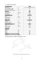
4. TECHNICAL FEATURES Symbol of conveyor Performance Max transportation length Max transportation height Diameter of transportation pipe Fan – t ype Rotational speed Air flow rate Total pressure Electric engine – type Power Rotational speed Supply voltage Rated current Feeder – type Diameter Number of chambers Rotational speed Feeder electric engine – type Power Rotational speed Supply voltage Rated current Dimensions: Length Width Height Weight Noise level Operation t/h m m mm rev/min m3/h Pa kW rev/min V A mm pc. rev/min Operating parameters of S 1000 in suction and force version Fig. 2. Pattern...
Open the catalog to page 11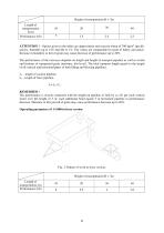
Height of transportation H = 3m Length of transportation L(m) Performance (t/h) ATTENTION ! – figures given in the tables are approximate and concern wheat of 700 kg/m3 specific gravity, humidity up to 14% and dirt to 1%. The values are comparable for grain of barley and maize. Increase in humidity or dirt of grain may cause decrease of performance up to 20%. The performance of the conveyor depends on length and height of transport pipeline as well as a kind and features of transported grain (moisture, dirt level). The total transport length equals to the length of all vertical and horizontal...
Open the catalog to page 12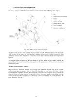
Pneumatic conveyor S 1000 in suction and force version consists of the following units - Fig. 4. 1 – fan 4 4 – suction cyclone 5 – compl. suction hose 6 – bend connector 7 – electrical installation tabliczka znamionowa Fig. 4. S 1000 in suction and force version. The drive of the fan of S 1000 contains electrical engine 7,5 kW. Rotational speed of the fan equals 2920 rev/min. At the side of air inlet, the fan is attached to the suction cyclone by means of bend connector, whereas outlet of the fan is connected by feeder pipe to the vane feeder and transportation pipeline. The suction cyclone is...
Open the catalog to page 13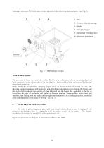
Pneumatic conveyor S 1000 in force version consists of the following units and parts – see Fig. 5.: 1 – fan 2 – framework/undercarriage 3 – feeder 4 – charging hopper 5 – horizontal throttling valve 6 – electrical installation tabliczka znamionowa Work in force system: The conveyor in force version works without flexible hose and nozzle, without suction cyclone and bend connector. At the side air inlet of the fan, there is a horizontal throttling valve assembled instead of the bend connector. Grain should be provided into charging hopper fixed on feeder instead of suction cyclone. The charging...
Open the catalog to page 14All Assentoft Silo catalogs and technical brochures
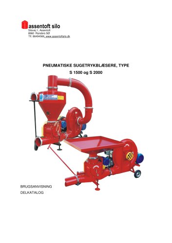 S1500 og 2000
49 Pages
 T 207
T 20749 Pages
 Reactor tanks for biogas
12 Pages
 Sealed storage
16 Pages
