
- Catalogs
- Assentoft Silo
- S1500 og 2000

S1500 og 2000
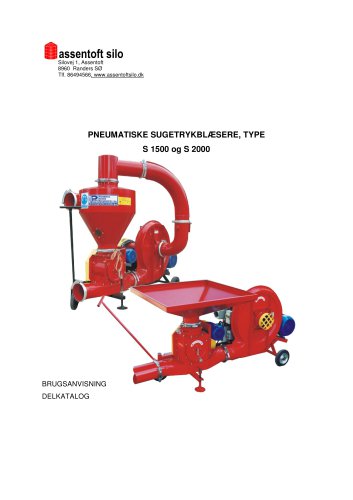
S1500 og 2000
This document serves as a user manual and parts catalog for pneumatic suction blowers, models S 1500 and S 2000, designed for transporting grains and other loose materials. It includes safety certifications and stresses the importance of reading the manual for proper operation and maintenance.
Only qualified adults should operate the equipment, adhering to safety regulations. Key safety measures include using sealed cables in damp environments, checking connections after long pauses, and ensuring no foreign objects are in the blower before use. Maintenance should be performed only when the machine is off and unplugged.
The blowers' transport capacity varies with the height and distance of transport. Specific motor and electrical requirements, including voltage and amperage, are detailed for models S 1500 and S 2000. The document provides comprehensive technical data, including motor types, speeds, and dimensions.
The blowers comprise several components such as a fan, frame, cell feeder, cyclone, and various pipes and connectors. The document details the assembly and function of each part, highlighting the importance of proper connection and maintenance.
Detailed diagrams and instructions for electrical installation are provided, covering motors, switches, and protective devices. Correct electrical setup is crucial to prevent damage and ensure safe operation.
Instructions for starting and stopping the motors are included, along with guidelines for regular maintenance and troubleshooting. Regular checks and adherence to operational procedures are essential for longevity and efficiency.
A list of warning symbols and their meanings is provided, emphasizing the need to keep these symbols visible and legible. Prohibited actions are outlined to prevent accidents and equipment damage.
Details on the electrical connections, such as the supply line with a 32 A or 63 A plug, and the operation of switches and buttons for starting and stopping the main supply and cell feeder are included.
Before starting, ensure the blower is on a stable surface, connected to a power source with the correct voltage and protection, and properly grounded. Assemble the blower and ensure all components are level and properly connected.
Verify that the suction head is not submerged in grain and ensure all switches are in the correct positions before operation. Follow a specific sequence to start the blower to avoid damage. Stop immediately if the blower vibrates or makes excessive noise and investigate the cause.
Specific procedures must be followed to ensure the correct mixture of grain and air in the transport line. Adjustments can be made using the suction head to optimize capacity. For pressure systems, ensure the system is airtight to prevent damage.
Daily checks should ensure the blower is complete and all connections are secure. Periodic maintenance includes checking belts, chains, and electrical components. Proper tensioning of belts and chains is crucial for optimal performance.
For short-term storage, protect the blower from weather conditions. Long-term storage requires additional maintenance. During disposal, recycle metal parts and responsibly scrap non-reusable parts.
The blower is partially disassembled for shipping and must be transported following safety regulations.
The product complies with applicable standards and safety and occupational hygiene regulations. It is intended for transporting grain and loose materials both horizontally and vertically and has been positively evaluated for safety and hygiene requirements.
The guarantee is valid for 12 months from the date of sale. Warranty service is provided on behalf of the manufacturer, and the warranty certificate must be presented for claims.
Catalog excerpts
Silovej 1, Assentoft 8960 Randers SØ Tlf. 86494566, www.assentoftsilo.dk PNEUMATISKE SUGETRYKBLÆSERE, TYPE S 1500 og S 2000 BRUGSANVISNING DELKATALOG
Open the catalog to page 1
PNEUMATISKE SUGETRYKBLÆSERE (RØRDIAMETER 160 mm) KTM (Vare- og Materialekode) PKWiU (Polsk produkt- og serviceklassifikation) 29.22.17- 10.20 KTM BRUGSANVISNING DELKATALOG 2. UDGAVE
Open the catalog to page 2
19 Delkatalog over reservedele 31
Open the catalog to page 3
1. INTRODUKTION Brugsanvisningen hører med til maskinens basale udstyr. De pneumatiske sugetrykblæsere/transportører, S 1500 og S 2000 har et certifikat for sikkerhedsmærket nr 342/2002 med gyldigheds periode fra 09.06.2002 til 08.06.2005 udstedt af Produktercertificerings Enhed IBMER i Warszawa. Nedenstående brugsanvisning bør læses af brugeren, der betjener blæseren samt af personer, der gennemfører reparationer og vedligeholdelse. Forstår man ikke brugsanvisningen, kan man få den forklaret hos produktets forhandler, som er: Assentoft Silo A/S Den pneumatiske sugetrykblæser bør betjenes af...
Open the catalog to page 4
1) Før drift påbegyndes skal man læse denne brugsanvisning. 2) Blæseren bør kun betjenes af en voksen, ansvarlig person. 3) Før første igangsætning skal en elektriker koble transportøren til nettet og checke om nulstillings- og beskyttelsesbestemmelser er opfyldt. 4) Blæseren skal sættes i gang som anført i afsnittet „Prøveigangsætning”. 5) Det er forbudt at sætte blæseren i gang, når reguleringsspjældets automatiske håndtag er løsnet, dvs. i placering “drift”. 6) Før begyndelse af drift, skal det checkes, at der ikke er fremmedlegemer i blæseren. 7) I tilfælde af strømafbrydelse eller afkobling...
Open the catalog to page 5
BEMÆRK !!! DET ER FORBUDT AT : 1. Arbejde uden skærme på rem- og kædetransmissionen eller med beskadigede skærme. 2. Kigge ind i kornets udløbshul, når transportøren er i drift 3. Sætte celleføderen i drift, når cyklon eller tragt er fjernet 4. Arbejde uden anvendelse af kobberwire på blæserens sugeledning 3. SIKKERHEDSSYMBOLER På nedenstående tavle er sikkerhedssymbolerne, placeret på blæseren, beskrevet. Sikkerhedssymboler er placeret på blæserens dele ifølge fig. 1. Sikkerhedssymboler og –mærker skal være rene, læselige samt beskyttet mod beskadigelse, snavs eller overmaling. Ødelagte og ulæselige...
Open the catalog to page 6
Mærkeskilt Maskinens symbol Placering af sikkerhedssymboler og skrifter på transportøren S 1500 og S 2000 Udsigt
Open the catalog to page 7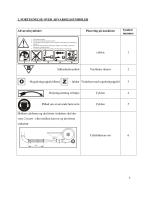
2. FORTEGNELSE OVER ADVARSELSSYMBOLER Symbol nummer Ventilator skærm 1- læs brugsanvisningen 2- forbud mod at betjene maskinen af børn 3- man må ikke koble anlægget til nettet i tilfælde af beskadigelse af tilslutning og stikdåsen 4- der skal anvendes behørige tilslutninger (stikdåse, stik, ledning ) med testet effektivitet i brandbeskyttelse 5- man skal koble anlægget fra strømmen før begyndelse af reparationen – Reguleringsspjæld åbent - lukket Vinkelrør med reguleringspjæld Påbud om at anvende høreværn Mellem cyklonen og det første vinkelrør skal der være 2 m rør - eller mellem kurven
Open the catalog to page 8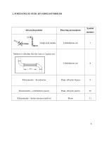
2. FORTEGNELSE OVER ADVARSELSSYMBOLER Undgå skrå rørdele Symbol nummer Klistermærke – hovedmotor Plade, afbryder skærm Klistermærke – celleføderens motor Plade, afbryder skærm Klistermærke – beskyt motoren mod sol Mellem to vinkelrør skal der være
Open the catalog to page 9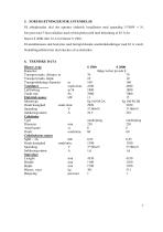
5. FORUDS^TNINGER FOR ANVENDELSE Pa arbejdsstedet skal der oprettes elektrisk installation med spending 3*380V + N, forsynet med 3-faset stikdase med et beskyttelsesstik med belastning af 63 A for blsser S 2000 eller 32 A for blsser S 1500 . El-installationen skal beskyttes med hurtigtvirkende smeltetradssikringer med 63 A v$rdi. Nulstillingseffektivitet skal checkes af en elektriker. Blaser, type Kapacitet Transport maks. distance m Transport maks. h0jde Transportlednings diameter Ventilator S 1500 S 2000 if0lge tavlen pa side 8 Luftforbrug Totalt tryk Elektrisk motor Motortype Omdr.hastighed Spending Indikeringsstr0m Cellef0der Type Diameter Antal...
Open the catalog to page 10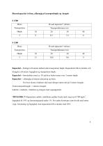
Blaserkapacitet i t/time, afhangig af transporthpjde og -langde Kapacitet - betinget af kornets t0rhed samt transportens h0jde. Kapaciteten bliver mindre ved for0gelse af kornets fugtighed og transportens h0jde. Kapacitet - formindskes med ca. 4% pa hver lodret meter over 3 meters h0jde Kapacitet - afhsngig af r0renes placering og form. For hver ekstra vinkelr0r skal man tilregne r0rets del pa 5 meters lsngde. Total transportlsngde = r0renes lsngde: lodrette, vandrette, vinkelr0r og slangen med sugeapparatet BEM^RK !!! Kapaciteter anf0rt i tabellerne gilder hvede med v$gt op til 700 kg/m , fugtighed...
Open the catalog to page 11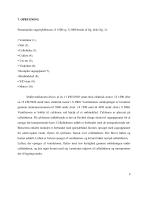
7. OPBYGNING Pneumatiske sugetrykblæsere, S 1500 og S 2000 består af flg. dele (fig. 2): • Ventilator (1), • Stel (2), • Celleføder (3), • Cyklon (4), • 2 m rør (5), • Vinkelrør (6), • Komplet sugeapparat (7), • Rørbindeled (8), • Y/D start (9), • Motor (10). Stråleventilatoren drives af en 11 kW//2920 omdr./min elektrisk motor i S 1500 eller en 15 kW/2920 omdr./min. elektrisk motor i S 2000. Ventilatorens omdrejninger er forstørret gennem remtransmissionen til 3860 omdr../min. i S 1500 samt til 4450 omdr../min i S 2000. Ventilatoren er koblet til cyklonen ved hjælp af et rørbindeled. Cyklonen...
Open the catalog to page 12
Den pneumatiske transportør S 1500 og S 2000 i den sugende og trykkend
Open the catalog to page 13
Elektrisk installation i blsser S 1500 - fig. 3. Elektrisk installation i blsser S 2000 - fig. 3a. El-installationen bestar af: - Elektrisk motor kW omdr./min - Elektrisk motor kW omdr./min - afbryder “stjerne/trekant” med omradet: A - automatisk afbryder M633: A Elektriske motorer beskyttes ved hjslp af automatiske afbrydere forsynet med termiske og kortslutningsudl0sere. Automatiske afbryderes termiske indstillere skal indstilles pa de enkelte motorers indikeringsstr0m. Pa grund af en stor igangsstningsstr0m idriftsstter man ventilatorens motor med hjslp af afbryderen “stjerne/trekant”....
Open the catalog to page 14All Assentoft Silo catalogs and technical brochures
 T 207
T 20749 Pages
 S 1000
42 Pages
 Reactor tanks for biogas
12 Pages
 Sealed storage
16 Pages
