300PB
1 /7Pages

300PB
1 /7Pages
Catalog excerpts

SELF-PRIMING POLY CENTRIFUGAL PUMPS INSTRUCTION MANUAL BANJO CORPORATION | A Unit of IDEX Corporation 150 Banjo Drive, Crawfordsville, IN 47933 U.S.A. banjocorp.com | Telephone: (765) 362-
Open the catalog to page 1
Read these instructions and the instructions covering operation of the pump drive unit. The gas engine (if so equipped) is shipped with no oil. Consult your owners manual for specific oil recommendations, maintenance procedures, schedules, and troubleshooting. The maximum angle of operation for gas engine drive units is 25° in all directions. For engine warranty service contact your local engine dealer. Make certain that all hose and pipe connections are air tight. An air leak in the suction line may prevent priming and will reduce the performance of the pump. Always place the pump as close to...
Open the catalog to page 2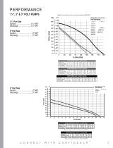
Note: Curve based on water and pump spinning at 3450 RPM PSI FT Head flow curve for Note: Curve based on water and pump spinning at 3450 RPM
Open the catalog to page 3
Remove the 10 body screws (12720), lock washers (V07018) and nuts (V07019) from the pump assembly. Remove the body from the pump assembly. Remove the check valve (12705) from the volute (13702). Remove the one upper volute screw (12900) and the two smaller volute screws (12725) from the volute. Remove the volute from the remaining pump assembly. Remove the check valve (12705) from the volute (12702A/13702). 4A: Screw the supplied 7/16-14 hex head cap screw into the impeller snout. As the bolt is tightened the impeller will be pried off of the shaft of the drive unit. Remove the 7/16-14 screw...
Open the catalog to page 4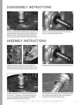
Remove carbon seal half from rear bracket with a round object. Tap gently with a hammer. Take care not to crack seal if reusing. Once disassembled; clean all reusable parts thoroughly, removing any traces of old gasket material and trapped / dried liquids from pump. At this time, it may be necessary to polish the drive unit shaft to remove any corrosion that may have formed. Install the pump slinger (12706) on to the drive unit shaft. The slinger should be slid all the way back on the shaft of the drive unit so that the slinger covers the step on the drive unit shaft as shown. Place the seal...
Open the catalog to page 5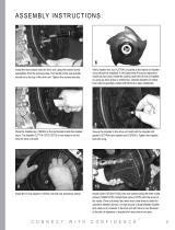
Install the rear bracket onto the drive unit using the bracket screw assemblies from the previous step. The handle of the rear bracket should be to the top of the drive unit. Tighten the screws securely. Verify impeller hex nut (12775A) is located at the bottom of impeller snout (should be installed). A very light press fit may be required to install nut into cavity. Install the ceramic seal half into hub of impeller by using an arbor press or similar tool. Outside diameter of rubber boot may be sparingly coated with silicone to ease installation. Place the impeller key (12902A) in the slot located...
Open the catalog to page 6
Place the pump body O-ring (12719A) around the outside flange of the rear bracket. The O-ring may be sparingly lubricated with silicone to ease installation of the pump body in the next step. Install the pump body (12712/13712) as shown below with the outlet flange facing up. Install the 10 body screws (12720), 10 lock washers (V07018), and 10 nuts (V07019) to secure the pump body to the rear bracket. Tighten the bolts securely all the way around. Please see banjocorp.com for more information BANJO CORPORATION A Unit of IDEX Corporation 150 Banjo Drive Crawfordsville, IN 47933 U.S.A. Telephone:...
Open the catalog to page 7All Banjo Corporation catalogs and technical brochures
 222PIH5
1 Page
 200PH6 Pump Flowchart
1 Page
 150P-3
1 Page
 Catalog 2020
176 Pages
 BANJO liquid Handing Products
172 Pages
 Manifold
3 Pages
 DRY-MATE ™
4 Pages


- Irrigation pump
- Irrigation valve
- Control valve
- Electric pump
- Impeller pump
- Plastic coupling
- Self-priming pump
- Straight coupling
- Hydraulically-operated pump
- Polypropylene irrigation fitting
- Elbow irrigation fitting
- Male compression irrigation fitting
- Irrigation solenoid valve
- Stainless steel valve
- On/off solenoid valve
- PTFE valve