- Catalogs
- Behlen Country
- 70112-Poly-Electric-Drinkers
70112-Poly-Electric-Drinkers

70112-Poly-Electric-Drinkers
Behlen Country provides quality products, including Poly Electric Drinkers, designed for durability and efficiency. This document outlines the installation, operation, and maintenance procedures for models AHW30, AHW60, AHW80, and AHW250.
- Location Preparation: Install the drinker on a minimum 4-inch thick concrete base, slightly raised for drainage. Ensure water and electricity connections are made through a 4-inch or larger tile, with the tile edge raised above the concrete to prevent water ingress.
- Drinker Placement: Drill holes in the concrete using the drinker's hold-down tabs as a guide. Use insulation board and weatherstrip to seal the drinker to the base.
- Water Line Connection: Use the supplied high-pressure ¾” I.D. hose and ensure a shut-off valve is accessible. A Shut-off Kit is available for winter shutdowns.
- Electrical Connections: Must be performed by a qualified electrician, following ASAE farm wiring recommendations and local codes. Proper grounding and fuse sizing are critical.
- Float Adjustment: Adjust the float to maintain a water level 1” to 1½” below the trough top.
- Valve Assembly: Attach the float and arm to the Franklin BL Valve using a thumb screw. Adjust the water level by positioning the float and arm appropriately.
- Ice in Trough: Check fuses, circuit breakers, and ensure proper sealing against cold air.
- Water Freezing: Ensure proper installation of supply lines and check for insulation and air gaps.
- Valve Issues: Adjust the float, check for debris, and ensure proper water pressure.
- Low Water Flow: Check for blockages, kinks, and ensure system pressure is adequate.
- Instructions are provided for cleaning the valve and replacing the plunger and seal rubber, ensuring optimal operation.
Behlen Country Electric Drinkers come with a 5-year limited warranty on the body and a 1-year limited warranty on valves and controls.
Catalog excerpts

Poly Electric Drinkers (Models AHW30, AHW60, AHW80, AHW250) THANK YOU FOR PURCHASING THIS PRODUCT Behlen Country has been in the business of providing quality products for more than 80 years. Our products will provide many years of service when maintained by the owner and used in accordance with the capabilities of the product. For questions about this product, or for parts inquiries, please contact our Customer Service Center listed below. Before beginning, read instructions thoroughly and inspect parts listing to insure that all parts have been included. Install drinker on a 4” (minimum) thick concrete base, slightly raised for better drainage. Before pouring concrete, have the water and electricity connected up through a 4” or larger tile for final connections to the drinker. Be sure the edge of the tile is slightly raised above the concrete (approx. 1-1/2”) so that water drainage does not go into the open tile. The tile must be left open to give access to warmer air below the frost line, thus preventing the riser from freezing. Be sure the riser pipe does not touch the sides of the tile. Note: The concrete pad should be at least 4” larger than the poly drinkers on all sides. Place the drinker in the desired position and drill 3/8” dia. x 1-1/2” (min.) deep holes, in the concrete using the molded-in hold down tabs at the base of the drinker as a guide. Cut the proper size hole in the 1” insulation board to fit over the riser tile. It is important to use this insulation board to help insulate and seal the bottom of the drinker. Enough 1” x 3/8” weatherstrip is included with your drinker to seal the bottom of the drinker to the concrete base and also to seal the float cover to the drinker. Put weatherstrip on the bottom of the drinker where it contacts with the concrete base. If there are any gaps bigger than 3/8”, two layers of weatherstrip can be put together to fill the gap. Please refer to the sketch in these sheets for proper placement of weatherstrip on the float cover. Secure the drinker using 3/8” x 1-7/8” expandable anchor bolts (purchased locally). Water Line: For connection of the drinker to the riser pipe, a high pressure %” I.D. hose is supplied with the drinker. A shut off valve which is easily accessible should be used at each drinker. If the drinker is to be shut down for the winter, a Shut-off Kit (Item No. 54130168) that drains the riser pipe to prevent freezing is available. The supply line should be flushed before drinker is connected. NOTE: Your drinker is equipped with a BL valve that is easy to clean and adjust. If low water pressure conditions exist and a higher flow rate is desired, a larger inlet is available (54300968) to increase the flow. (For hookup instructions see Technical Information 70131). Electrical Connections (for AHW30, AHW60, AHW80 & AHW100 models only): NOTE: Electrical connections should be made by a qualified electrician. The black wire from the power supply must be connected to the thermostat and the white wire from the supply connected to the white wire on the heating pad. The grounding wire from the supply must be connected to the terminal in the electrical box of the drinker. The unit must be properly grounded to the supply box and fused properly. The fuse size is indicated on the red ground instruction tag. Behlen COUNTRY CUSTOMER SERVICE CENTER PO Box 569 Ph: 800-447-2751
Open the catalog to page 1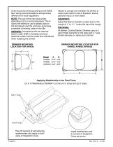
Units should be wired according to the ASAE farm wiring recommendations except where different from local regulations. Failure to comply and maintain the drinker to code could result in loss of livestock, severe personal injury, or even death. NOTE: The use of the riser pipe as the grounding rod is not recommended. This is due to the extensive use of plastic pipe on the farmsteads and the unknown grounding properties of existing pipe on the site. WARNING: Compliance with the national electric code (CSA in Canada) and local electrical codes must be made and maintained when installing the drinker....
Open the catalog to page 2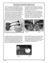
Instructions How To Assemble The Float And Arm To The Franklin BL Valve And How To Adjust The Valve The Franklin Valve is already attached to the drinker. The float and arm assembly is with the hardware kit. They are packaged separately to prevent undue wear to the valve caused by the arm bouncing up and down during shipping. The float and arm are attached to the valve by a thumb screw. The float can be positioned either closer or further away from the valve (see photo below left for the two float positions). Further away increases the shut off force of the valve. However depending upon which drinker...
Open the catalog to page 3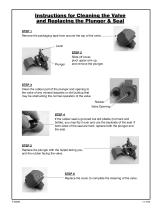
Instructions for Cleaning the Valve and Replacing the Plunger & Seal STEP 1 Remove the packaging tape from around the top of the valve. Lever STEP 2 Slide off cover, pivot upper arm up, and remove the plunger. STEP 3 Clean the rubber part of the plunger and opening to the valve of any mineral deposits or dirt buildup that may be obstructing the normal operation of the valve. Rubber Valve Opening STEP 4 If the rubber seal is grooved but still pliable (not hard and brittle), you may flip it over and use the backside of the seal. If both sides of the seal are hard, replace both the plunger and the...
Open the catalog to page 5All Behlen Country catalogs and technical brochures
 Magnum Dog Kennel
2 Pages
 70141-Haysmart-Bale-Feeders
2 Pages
 70090-MX-V-Chute
2 Pages
 70076-M1-Squeeze-Chute
14 Pages

- Jympa field cultivator
- Jympa mounted field cultivator
- Drinking system
- Vertical tiller
- Jympa field cultivator with roller
- 2-section disc tiller
- Grooming mower
- Power cultivator
- Gate
- Livestock gate
- Metal gate
- Rear-mount grooming mower
- Metal waterer
- PTO-driven grooming mower
- Trough waterer
- Plastic drinking system
- Agricultural rotary cutter
- Cattle waterer
- Mounted disc tiller
- Loadout