- Catalogs
- Bird Gard LLC
- Bird Gard PRO
Bird Gard PRO

Bird Gard PRO
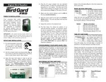
The Bird Gard® Pro kit includes a control unit with a built-in speaker, mounting bracket, and AC power adapter. An optional battery clip and extension speaker are available. Ensure the power switch is off and the volume is set to minimum before powering up.
1. Mount the unit on a post or surface facing the affected area using the provided bracket and screws.
2. Open the front panel to set the Recording, Mode, Time Off, Time of Operation, and Random Operation switches.
3. Connect the power adapter to an outlet or attach the battery clip to a 12V battery.
4. Set the volume to low and slide the power switch to INT/EXT. SPKR position.
5. Adjust the volume as needed and connect an optional extension speaker if required.
Use a small tool to toggle switches in the switch array for programming.
Recording Setting Switches: Control which bird sounds are played.
Mode Setting Switches: Set operation modes, including time intervals and random mode.
Time Off Switches: Determine delay intervals between sounds.
Time of Operation Switches: Set operation times (day, night, or 24-hour).
Random Operation Switch: Enable or disable random playback of sounds.
Bird Gard offers a one-year limited warranty for replacement, repair, or refund. Liability is limited to the purchase price, and no consequential damages are covered.
Common issues include no sound, repetitive playback, and improper operation in day/night modes. Solutions involve checking settings, resetting the unit, and ensuring the photocell is unobstructed.
The volume control dial adjusts sound output. The power switch should be left off for 30 seconds before turning back on to reset electronics.
Catalog excerpts
4) Plug the AC power adapter into any standard electrical outlet. Or attach the optional battery clip assembly to a 12V battery. The other end of the cable should already be plugged into the power jack located above Power on the back of the unit. Digital Bird Repeller 5) Make sure the volume setting is set to LOW (all the way counterclockwise). 6) Slide the power switch to the right to the INT/EXT. SPKR position. The unit may take a few seconds before starting. Your complete Bird Gard® Pro kit includes a conrol unit t with built-in speaker, mounting bracket and AC power adapter. (An optional battery clip assembly is available; an optional speaker may be plugged into the speaker jack on the back of the unit.) 7) Adjust the volume to the desired level. IMPORTANT: Be c ertain that the power switch is in the OFF s i ion and the volume ontrol is set to the po t c m inimum (LOW) v olu me level (c ount erc lockw ise) as shown in Fig. 1 when powering up the unit. SETUP AND INSTALLATION 1) It is recommended to mount the unit on a post or surface that is positioned in the direction and at the same level of the infected area. PROGRAMMING YOUR BIRD GARD® PRO Fig. 1 2) Use the included metal mounting bracket (Fig. 2) and screws (2) with lock washers (2) to mount the unit to a post, fence, wall or other surface. 3) Open the clear front panel in order to set the Recording Switches, Mode Setting Switches, Time Off Switches, Time of Operation Switches and Random Operation Switch to the desired settings. (See “PROGRAMMING YOUR BIRD GARD® PRO” for more programming details.) Extension Speaker 8) The Bird Gard® Pro allows the addition of an optional extension speaker. An extension speaker may be operated as a “stand-alone” speaker OR along with the internal speaker in the front of the Bird Gard® Pro unit. Plug in the Extension Speaker into the jack on the back of the unit. Then move the slide switch on the front of the control panel (upper right hand corner) to INT/EXT. SPKR (to operate BOTH speakers) OR to EXT. SPKR ONLY (to operate ONLY the Extension Speaker). To program your Bird Gard® Pro unit you will need a small screw river, toothpick, or other pointed, rigid d object to toggle the switches in the switch array (Fig. 3). The switch array banks are located in the bottom right hand corner on the front of the unit (to the right of “RECORDINGS”) inside the front cover door. A switch is ON if the switch is pressed down on the right-hand side. The switch is OFF if the left side is pressed down. RECORDING SETTING SWITCHES The RECORDINGS switches are the first eight switches in the switch array. Each switch has a recording number to the right of it that corresponds with the bird descriptions listed on the foil label affixed on the front inside the front cover door. MODE SETTING SWITCHES The Mode Setting switches set the arious modes v of operation: such as the amount of time between playing bird distress calls, when the unit will perate (day only, night only, o or 24 hours), and whether the unit will operate in the Random Mode or ormal Mode. N Mode or Function Sets the Time-Off Period Sets the Time-Off Period Sets the Time the unit plays Sets the Time the unit plays Turns Random Mode On or Off The two Time-Off switches are located just below the Recording switches in the switch array. When the unit is set to one of the various T ime-Off modes, the unit will delay a number of s econds or minutes between recorded sounds. Please note that the unit will play all of the elected s recordings (either equentially or on-sequentially, s n depending on the Random Mode) then it will go into a delay. The unit will play for a short interval of time, from 6 seconds to 48 seconds, depending on the number of sounds that are selected. The time the unit stays off depends on the Time-Off and the Random Mode settings. If the unit is op r t ea ing in Random Mode, the unit will delay anywhere from the min um value to the maximum value for im that Time-Off setting. If the unit is not in Random Mode, it will delay only the inimum value. To m set the Time-Off period (or delay interval), use the f ollowing ettings on switches 1 and 2 in the mode s function settings. Switch 1 Switch 2 ON OFF
Open the catalog to page 1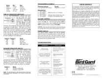
Mode Short Medium Long XLong MODE SETTINGS Mode Day Only 24-Hour Night Only also Night Only TIME OF OPERATION SWITCHES The two “DAY/24HR/NIGHT” switches are located just under the Time-Off switches in the bottom switch array. ‘Night Mode’ operates the unit at night and ‘Day Mode’ operates the unit during the day. However, the photocell that senses the sunlight is susceptible to bright lights. Take care not to have bright lights shining towards the unit since this can prevent the unit from operating properly. In 24HR mode, the unit will operate continuously, regardless of the time of day. To set...
Open the catalog to page 2All Bird Gard LLC catalogs and technical brochures
 Bird Gard SUPER PRO PA4
2 Pages
 Bird Gard SUPER PRO AMP
12 Pages
 Bird Gard SUPER PRO
12 Pages
 Bird Gard PRO PLUS
2 Pages