7300
7300
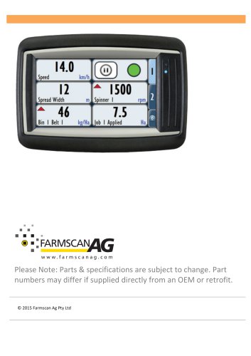
The 7000 series is a versatile device for agricultural systems, featuring a 4.3” color touchscreen. It supports multiple inputs and outputs, configurable in metric and imperial units, and interfaces with various agricultural applications.
The terminal includes a RAM style mount, a 4.3” TFT display, and a 32-bit processor. It supports interfaces like CANbus, RS-232, USB, and optional Ethernet, operating on 8-36V DC with IP67 and IP65 protection.
The Farmscan Ag Spreader Controller 7300 offers advanced control with a "TILE" user interface, supporting manual, automatic, and GPS modes, and data export in CSV format.
The monitor kit includes a 7000 Monitor/Controller, in-cab harness, RAM mount kit, and CANbus terminator. The UniPOD kit includes a UniPOD with spreader software and a sensor harness.
Includes steps for mounting the terminal, connecting power, CANbus, and UniPOD, and installing sensors like wheel, spinner, and belt sensors.
Connect power after installation, directly to a 12 Volt DC battery, avoiding starter motor or alternator connections.
Use the 4 Way Deutsch plug for CANbus communications, avoiding running the harness alongside other cables.
Mount the UniPOD with cables facing downwards in a weather-sheltered position.
Features a settings menu, display tiles, and tabs for different data sets. LED status lights assist in troubleshooting.
Allows setup of the 7300 series with options for setup, jobs, alarms, and maintenance menus.
Includes adding, removing, and editing users, with permissions for various functions.
Configure spreader setup, control speeds, measurements, and CANbus connections.
Set minimum speed, slow hold speed, and prime mode for spreader operation.
Configure gate width, sensor calibration, roller diameter, and belt motor setup.
Configure spinners, calibrate motors, and enable ramp control for gradual starts.
Configure spread widths and calibrate speed sensors, choosing between GPS and standard inputs.
Export job data via USB for use in farm software supporting CSV files.
Customize front screen tiles, adjust brightness, and switch unit types. Day/Night mode changes display settings.
Catalog excerpts
Please Note: Parts & specifications are subject to change. Part numbers may differ if supplied directly from an OEM or retrofit. © 2015 Farmscan
Open the catalog to page 1
TABLE OF CONTENTS INTRODUCTION ABOUT THE 7000 ABOUT THIS GUIDE TECHNICAL SPECIFICATIONS PARTS LIST CHOOSING A SCREEN LOCATION MOUNTING HARDWARE CONNECTION TO POWER CONNECTION TO UNIPOD RUNNING THE CABLES MOUNTING THE UNIPOD UNIPOD STAUS LIGHTS SENSOR CONNECTIONS INSTALLATION (SENSORS) WHEEL SENSOR WHEEL SENSOR INSTALLATION PROCEDURE GPS SPEED INSTALLATION SPINNER SENSOR INSTALLATION BELT SENSOR INSTALLATION BIN LEVEL SENSOR (OPTIONAL) FLOW CONTROL VALVE ( FCV) 7300 GENERAL OVERVIEW ONLY FRONT SCREEN -‐ OVERVIEW LED STATUS LIGHTS -‐ OVERVIEW SETTINGS MENU -‐ OVERVIEW SETUP (1) -‐ OVERVIEW JOBS...
Open the catalog to page 2
7300 SERIES MANUAL V1 3 SPREADER SETUP (1) CONTROL (2) CONTROL SPEEDS (2A) AUXILIARY SETUP (2B) GATE SETUP (2C) BELT SETUP (2D) SPINNER SETUP (2E) MEASUREMENTS (3) SPREAD WIDTH SPEED-‐GPS (4) WHEEL SENSOR (DISPLAY SPEED CORRECTLY) GPS SERIAL SETUP CANBUS CAPACITY (2A) BELT RATE (3A) SPINNER RATE GATE (4A) TEST (5A) PRODUCT (6A) PRODUCT (CALIBRATION) PRODUCTS (TANK CALIBRATION) CREATING OR REMOVING A PRODUCT PRODUCT CALIBRATION CALIBRATION METHOD – BULK DENSITY DETERMINING BULK DENSITY SUPPLIER AND BATCH CREATING AN ALARM ALARM OPTIONS ACTIVATE \ DEACTIVATE ALARM EDITING AN ALARM DELETING AN ALARM...
Open the catalog to page 3
DAY/NIGHT MODE FRONT SCREEN CONTROL SPREADER BELT CONTROL SPREADER SPINNER CONTROL SPREADER APPLICATION RATE
Open the catalog to page 4
INTRODUCTION ABOUT THE 7000 The 7000 series is a versatile monitoring and control device that is capable of interfacing with many agricultural systems. A 4.3” colour touch screen provides a simple but powerful interface for operators as well as providing the ability to monitor multiple inputs at once. The display is fully configurable to show any combination of monitored values in both metric and imperial units. It is also configurable to let the operator control the system outputs by selecting onscreen buttons. The 7000 series devices have connections for a monitoring camera as well as many...
Open the catalog to page 5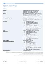
TECHNICAL SPECIFICATIONS TERMINAL Housing Display Processor & Memory Interfaces Video Connectors Power Supply Environmental Conditions Operating System RAM Style mount, orientation landscape Approx. W 142 x H 98 x D 49 mm, excl. connectors and cables Weight < 1 kg 4.3”, 16:9 , TFT, transmissive , 480 x 272 pixels 400 cd/m² max brightness , 400:1 max contrast H ±60°, V ±55° max viewing angle, resistive touchscreen 32-‐bit, 532 MHz, I.MX35 256 MB DDR2 , 1 GB Mass Storage, 32 kB serial EEPROM • 2 CANbus ISO 11898, • CAN specification 2.0 B active • 1 RS-‐232 (RxD, TxD, GND only), EIA-‐level • Optional...
Open the catalog to page 6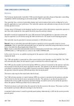
7300 SPREADER CONTROLLER OVERVIEW The Farmscan Ag Spreader Controller 7300 was developed to provide advanced Spreader controlling capabilities whilst maintaining an extremely simple “TILE” user interface. The controller has a variety of selectable display and control options that can be configured to suit a specific application or user preference. The controller options and calibration setup can also be locked to limit operator access. A large colour LCD (liquid crystal display) touchscreen gives all the information required to operate in one view with readouts for rate, speed, bin level, trip...
Open the catalog to page 7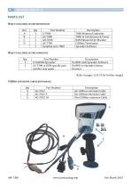
PARTS LIST WHAT’S INCLUDED IN THE M ONITOR KIT Ref Qty Part Number A 1 A-‐7000 B 1 AC-‐7000 C 1 AH-‐7000 D 1 AC-‐7700 1 Installed onto 7000 WHAT’S INCLUDED IN THE UNIPOD KIT Qty Part Number 1 A-‐UniPOD-‐Spreader 1 AC-‐7300 or OEM specific part number may apply Description 7000 Monitor/Controller 7000 In Cab Harness & Power RAM Mount Kit for Monitor CANbus Terminator Spreader Software Description UniPOD with Spreader Software UniPOD to Spreader Sensor Harness. Refer to pages 12 & 13 for further images CANBUS EXTENSION CABLES (OPTIONAL) Qty Part Number X AC-‐2012 X AC-‐2012-‐5 X AC-‐2012-‐10 Description...
Open the catalog to page 8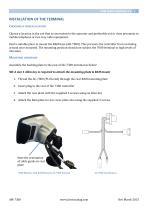
INSTALLATION OF THE TERMINAL CHOOSING A SCREEN LOCATION Choose a location in the cab that is convenient to the operator and preferably not in close proximity to mobile telephone or two way radio equipment. Find a suitable place to mount the RAM base (AH-‐7000). This prevents the controller from swiveling around once mounted. The mounting position should not subject the 7000 terminal to high levels of vibration. MOUNTING HARDWARE Assemble the backing plate to the rear of the 7300 terminal as below: NB: A size 4 Allen key is required to attach the mounting plate & RAM mount 1. Thread the AC-‐7000...
Open the catalog to page 9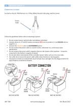
CONNECTION TO POWER Located on the AC-‐7000 harness is a 3 Way (Male) Deutsch style plug, used for power. Power Input Follow the guidelines below when connecting to power. • Do not connect power until all other installation is finished. • Connect direct to 12 Volt DC battery terminals, RED wire to positive (+) and BLACK wire to negative (-‐). • Connect the ORANGE wire to ACCESSORIES power • Do not connect the power cable to a starter motor, alternator etc., as this may cause interference. • Do not connect the power cable’s negative direct to the chassis of the machine – it must be connected to...
Open the catalog to page 10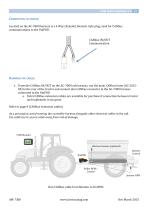
CONNECTION TO UNIPOD Located on the AC-‐7000 harness is a 4 Way (Female) Deutsch style plug, used for CANbus communications to the UniPOD. CANbus IN/OUT Communication 1. From the CANbus IN/OUT on the AC-‐7000 cab harness, run the main CANbus loom (AC-‐2012-‐ XX) to the rear of the tractor and connect into CANbus connector in the AC-‐7300 harness connected to the UniPOD a. Extra CANbus extension cables are available for purchase if connection between tractor and implement is too great. Refer to page 8 (CANbus extension cables) As a precaution, avoid running the controller harness alongside other...
Open the catalog to page 11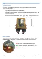
MOUNTING THE UNIPOD A UniPOD (ECU) & sensor adapter harness (AC-‐7300) is supplied with all systems to provide connection points for sensors. • Ensure the UniPOD is mounted as per example below. • Ensure that all cabling leaving the UniPOD faces downwards, so to prevent water entering the UniPOD or connections. • It is recommended, if possible to mount the UniPOD in a position sheltered from the weather. Status Lights UNIPOD STAUS LIGHTS The UniPOD has two (2) status indicator lights located as the TOP Right Hand Side of the UniPOD mainboard (Inside the enclosure). This should be left visible...
Open the catalog to page 12
Archived catalogs
 AgGuide
4 Pages
- Digital control system
- Crop input control system
- Spraying control system
- Touch screen control system
- Smart control system
- Seeding control system
- Connected control system
- ISO 11783 control system
- GPS control system
- Fertilizer application control system
- Automatic control system
- Harvesting control system
- Variable-rate control system
- Agriculture monitor