74v1
74v1
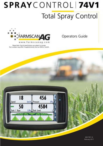
The 7000 series is a versatile monitoring and control device for agricultural systems, featuring a 4.3” color touch screen. It supports multiple inputs and outputs, configurable displays, and alarm settings for threshold breaches. Applications include spray, variable rate, and spreader rate controllers.
The device includes a RAM style mount, a 4.3” TFT display, and a 32-bit processor. It supports interfaces like CANbus, RS-232, USB, and optional Ethernet and video inputs. It operates in temperatures from -30°C to +75°C and has IP67 and IP65 ratings for environmental protection.
The 74V1 Spray Controller offers advanced spray control with a simple interface, supporting automatic and GPS-based modes. It maintains spray records and connects via CANbus to sensors and valves, supporting manual and automatic rate adjustments.
The monitor kit includes the 7000 Monitor/Controller, in-cab harness, RAM mount kit, and CANbus terminator. The UniPOD kit includes the UniPOD with sprayer software and necessary harnesses. Optional CANbus extension cables and Smart Switches are available.
Installation involves selecting a screen location, connecting power, and setting up CANbus communications. The UniPOD should be mounted with cables facing downward to prevent water ingress. Proper cable management is essential.
Two status indicator lights on the UniPOD mainboard indicate power connection and CANbus communications. Flashing lights indicate run mode.
Wheel sensors and GPS antennas are used for speed input. The control bank includes valves and sensors for spray operations, requiring upright installation.
Components include pressure relief valves, flow control valves, flow sensors, section valves, and pressure sensors, each serving specific functions in the system.
Steps include setting up CANbus/UniPOD, machine, implement/section widths, wheel/GPS input, tank, flow meter, alarms, jobs, and screen layout.
The Settings menu allows configuration of the 74V1 device, including setup, jobs, alarms, and maintenance. The Device menu covers tank settings, job management, alarms, and maintenance.
Includes control speeds, auxiliary setup, pressure sensor configuration, and speed source selection. CANbus and UniPOD connections are managed here.
Calibration can be done using manual factor or full system calibration methods, ensuring accurate flow measurement.
Jobs record operational data and can be exported. Alarms can be set for various parameters, affecting system operation.
Includes software updates, touch screen calibration, and backup/restore functions.
Allows settings backup, reset to default or backup settings, and import/export via USB.
Time and language settings can be updated, requiring a restart for changes.
Model swap allows changing controller models with necessary codes. User management includes adding, removing, and editing users with permissions.
Display settings include tab customization, brightness, and unit selection. Machine settings cover control speeds, auxiliary setup, and sensor configurations.
Details the connections for the UniPOD, including ground, flow valve, section controls, and CANbus connections.
Farmscan Ag Pty Ltd contact details are provided for inquiries.
Catalog excerpts
Operators Guide " ® 11 FARMSCANfl/jwww.farmscanag.com Please Note: Parts & specifications are subject to change. Part numbers may differ if supplied directly from an OEM or retrofit.
Open the catalog to page 1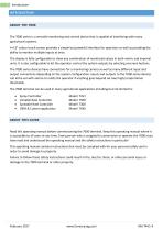
Introduction INTRODUCTION The 7000 series is a versatile monitoring and control device that is capable of interfacing with many agricultural systems. A 4.3” colour touch screen provides a simple but powerful interface for operators as well as providing the ability to monitor multiple inputs at once. The display is fully configurable to show any combination of monitored values in both metric and imperial units. It is also configurable to let the operator control the system outputs by selecting onscreen buttons. The 7000 series devices have connections for a monitoring camera as well as many different...
Open the catalog to page 3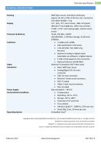
Technical Specifications TECHNICAL SPECIFICATIONS Copyright© 2010, Wachendorff Elektronik GmbH & Co. KG and Wachendorff Electronics USA, Inc. All rights reserved. All details are without guarantee. Errors and omissions excepted. CANopen ® is a registered community trade mark of CAN in Automation e. V. Linux® is a registered trademark of Linus Torvalds in the United States and other countries.
Open the catalog to page 4
74v1 Spray Controller 74V1 SPRAY CONTROLLER The Farmscan Ag Spray controller 74V1 was developed to provide advanced spray control capabilities whilst maintaining an extremely simple Tile & Tab user interface. The controller has a variety of selectable display and control options that can be configured to suit a specific application or user preference. The controller options and calibration setup can also be locked to limit operator access. The optional switch box controller incorporates 5 or 10 section control switches, master on/ off control and up/ down rate control. Spray control kits can...
Open the catalog to page 5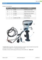
Parts List PARTS LIST ** Item D (CANbus Terminator) - Normally this will have an extension cable connected to this port that runs down to the UniPOD or a "Y" style cable for the Smart switch. The CANbus terminator will then plug into the harness at the UniPOD end. - CANbus OUT
Open the catalog to page 6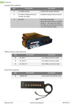
Parts List
Open the catalog to page 7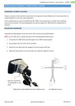
Installation of Terminal – Smart Switch - UniPOD INSTALLATION OF TERMINAL – SMART SWITCH - UNIPOD CHOOSING A SCREEN LOCATION Choose a location in the cab that is convenient to the operator and preferably not in close proximity to a mobile telephone or two-way radio equipment. Find a suitable place to mount the RAM base (AH-7000). This prevents the controller from swivelling around once mounted. The mounting position should not subject the 7000 terminal to high levels of vibration. MOUNTING HARDWARE Assemble the backing plate to the rear of the 74V1 terminal as described below: NOTE: A size 4...
Open the catalog to page 8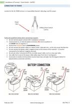
Installation of Terminal - Smart Switch - UniPOD Located on the AC-7000 harness is a 3-way (Male) Deutsch style plug, used for power. Follow the guidelines below when connecting to power: • Do not connect power until all other installation is finished. • Connect direct to 12 Volt DC battery terminals, RED wire to positive (+) and BLACK wire to negative (-). • Connect the ORANGE wire to ACCESSORIES power. • Do not connect the power cable to a starter motor, alternator etc., as this may cause interference. • Do not connect the power cable's negative direct to the chassis of the machine - it must...
Open the catalog to page 9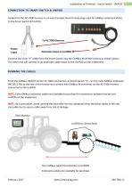
Installation of Terminal – Smart Switch - UniPOD CONNECTION TO SMART SWITCH & UNIPOD Located on the AC-7000 harness is a 4-way (Female) Deutsch style plug, used for CANbus communications to the Smart Switch & UniPOD To AC-7000 Harness Power Input Extension down to UniPOD Connect the inline “Y” cable from the Smart Switch into the CANBus IN on the harness as shown above. The other end will connect to an extension cable down to the UniPOD on the implement. From the CANbus IN/OUT on the AC-7000 cab harness or Smart Switch “Y”, run the main CANbus Extension (AC-2012-XX) to the rear of the tractor...
Open the catalog to page 10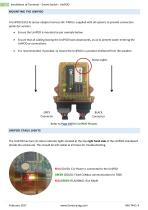
Installation of Terminal – Smart Switch - UniPOD MOUNTING THE UNIPOD A UniPOD (ECU) & sensor adapter harness (AC-740X) is supplied with all systems to provide connection points for sensors. Ensure the UniPOD is mounted as per example below. Ensure that all cabling leaving the UniPOD faces downwards, so as to prevent water entering the UniPOD or connections. It is recommended, if possible, to mount the UniPOD in a position sheltered from the weather. Status Lights GREY Connector BLACK Connector Refer to Page 100 for UniPOD Pinouts UNIPOD STAUS LIGHTS The UniPOD has two (2) status indicator lights...
Open the catalog to page 11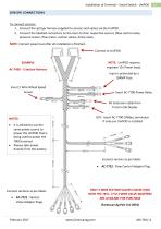
Installation of Terminal – Smart Switch - UniPOD SENSOR CONNECTIONS To connect sensors: 1. Connect the sprayer harness supplied to sensors and valves via the UniPOD. 2. Connect the labelled connectors on the loom to their respective sensors (flow control valve, pressure sensor, flow meter, section valves, dump valve. NOTE: Connect power last after all installation is finished. Connect to UniPOD NOTE: UniPOD requires separate 12v Power input. EXAMPLE AC-7405 - 5 Section Harness Input is protected by a 10AMP Fuse Insert 2 Wire Wheel Speed Sensor Insert AC-7700 Power Relay IN: Extension cable from...
Open the catalog to page 12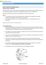
Installation (Sensors) The wheel sensor consists of a reed-type sensor (magnetic switch) and wheel magnet to be fitted onto any non-driven ground wheel of the sprayer. The magnet activates the sensor as it sweeps past. The spray controller requires at least one wheel pulse per second from the sensor. • In circumstances where an extremely large wheel is working at slow speeds (less than 5kph), additional wheel magnets may be fitted at equal spacing's. • Any sprayers that do not have a non-driven ground wheel can use a GPS speed sensor as an alternative. WHEEL SENSOR INSTALLATION PROCEDURE To install...
Open the catalog to page 13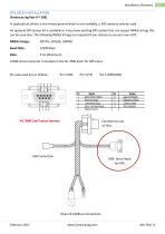
Installation (Sensors) In applications where a non-driven ground wheel is not available, a GPS antenna may be used. An optional GPS Sensor kit is available or if you have existing GPS system that can output NMEA strings this can be used also. The following NMEA Strings are required if you choose to use your own GPS: NMEA Strings: GPVTG, GPGGA, GPRMC Baud Rate: 19200 kbps A DB9 serial connector is located on the AC-7000 loom for GPS input. Pin outs used are as follows: Pin 2 (RX) Pin 3 (TX) Pin 5 (GROUND)
Open the catalog to page 14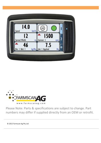
Archived catalogs
 AgGuide
4 Pages
- Digital control system
- Crop input control system
- Spraying control system
- Touch screen control system
- Smart control system
- Seeding control system
- Connected control system
- ISO 11783 control system
- GPS control system
- Fertilizer application control system
- Automatic control system
- Harvesting control system
- Variable-rate control system
- Agriculture monitor