- Company
- Products
- Catalogs
- News & Trends
- Exhibitions
Header Height Sensor Installation Guide
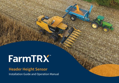
Header Height Sensor Installation Guide
The document stresses the importance of following safety warnings and cautions to prevent injury, death, and equipment damage. Key warnings include risks related to hydraulic pressure loss, unexpected machine start-up, electrical fires, and unstable working conditions. Cautions emphasize proper cable routing, battery safety, and avoiding pressure washing sensitive components.
What's in the Box
The kit contains Sensor A and B, sensor wires, CANbus M12 wire, Y-split for retrofit, and CANbus M12 terminator. Alcohol swabs are included for cleaning surfaces before installation.
System Diagrams
Diagrams show the wiring setup for both the Yield Monitor Pro and Legacy Yield Monitor installations, detailing connections between sensors, the ECU, and other components like the moisture sensor and optical sensors.
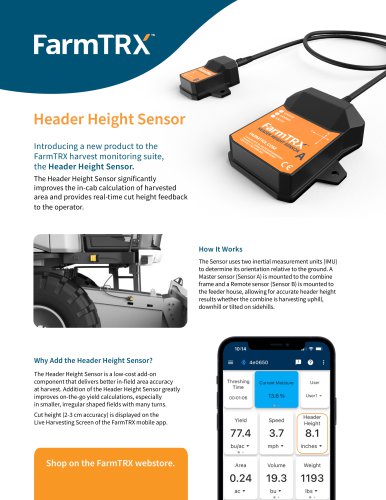
How It Works
The system uses inertial measurement units (IMUs) in each sensor to determine orientation relative to the ground. Sensor A is mounted on the combine frame, and Sensor B on the feeder house. The relative angle between the sensors determines the header height.
Installation Process
Installation involves selecting appropriate mounting locations for the sensors, ensuring one axis is parallel to the wheel axle. Detailed steps are provided for connecting sensors to the wire harness, including specific instructions for retrofitting to legacy systems.
Mounting Sensors
Sensors can be mounted using VHB tape or hard fastened with screws. Guidance is provided on preparing surfaces and securing sensors properly.
In-App Setup and Calibration
After installation, sensors must be calibrated using the FarmTRX mobile app. This involves orienting the sensor bodies and setting the maximum cutting height. Calibration ensures accurate header height readings during operation.
Operation
During harvesting, the header height can be monitored via the FarmTRX app. The app displays the active cutting height and indicates when the header is below the maximum harvesting height threshold.
Troubleshooting
Common issues include incorrect sensor orientation, CANbus errors, and improper sensor connections. Solutions are provided for each problem, such as re-calibrating sensors or checking wire connections.
Interpreting LEDs
LED indicators on the sensors provide status updates. Different colors indicate whether the sensor is calibrated, below or above the max harvest height, or if there are errors or warnings.
Catalog excerpts
Header Height Sensor Installation Guide and Operation Manual
Open the catalog to page 1
Version 1 Kit Numbers AG-HS-1000/1001 farmtrx.com
Open the catalog to page 2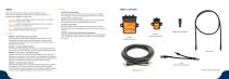
Safety Always follow the instructions that accompany a Warning or Caution. These notices are provided to help prevent injury, death, and equipment damage during installation or maintenance. • WARNING – Indicates a potentially hazardous situation that, if not avoided, could result in serious injury or death. • CAUTION – Indicates a potentially hazardous situation that, if not avoided, may result in minor or moderate injury. • NOTE – The absence of a warning doesn’t mean the task is risk-free. Always stay alert and follow safe work practices. Warnings • WARNING – Feeder house/Header Drop Hazard...
Open the catalog to page 3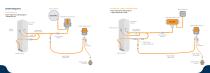
System Diagrams Yield Monitor 2.0/Plus+ (Retrofit Install) External Antenna External Antenna Header Height Sensor Wiring Diagram —Legacy Yield Monitor Installs Yield Monitor Pro Header Height Sensor Wiring Diagram —Yield Monitor Pro Yield Monitor ECU (In Cab) Clean Grain Elevator Clean Grain Elevator Header Height Sensor A Header Height Sensor A Optical Sensors Optical Sensors Interconnect Wiring Harness Interconnect Wiring Harness Primary Wiring Harness Primary Wiring Harness Y-Split Harness (Legacy installs only) Moisture Sensor Moisture Sensor Header Height CANbus Wire Header Height CANbus...
Open the catalog to page 4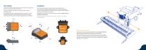
Each sensor contains an inertial measurement unit (IMU) which can determine the sensor’s orientation relative to the ground. When choosing an installation location, ensure there is enough free wire to accommodate completely lowering the feeder house. Sensor B will typically mount close to the hinge point of the feeder house to reduce the amount of distance it will travel when the feeder house lowers. Sensor A is mounted to a fixed point on the combine frame, Sensor B to the feeder house. Once calibrated, the relative angle between Sensor B and Sensor A is used to determine the height of the combine...
Open the catalog to page 5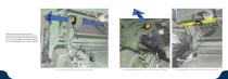
Determine the mounting location for Sensor A (parent sensor). Underneath the cab, there are many possible mounting locations that will allow the sensors X, Y or Z axis to run parallel to the combine’s front axle. The following photographs are of example installations. Z-Axis is parallel with the wheel axles—Connectors facing down Z-Axis is parallel with the wheel axles—Connectors facing back of combine Y-Axis is parallel with the wheel axles—Connectors facing back of combi
Open the catalog to page 6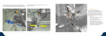
The same principles of mounting apply to Sensor B. It is usually the simplest to mount the sensor with the label facing up and connectors backwards, like shown in the previous images. Below are some examples of Sensor B mounting location. Once the ideal mounting location has been determined for your combine, proceed to the next step. Connecting to Wire Harness If you are attaching a Header Height Sensor to a legacy FarmTRX Yield Monitor (generation 2 or 3), skip to the section below labelled “Retrofit Install”. The Yield Monitor Pro comes with an M12 connector branching off the head of the Sensor...
Open the catalog to page 7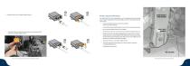
4. Thread the CAN wire on to Header Height Sensor A. 5. Thread the CAN terminator (set aside in step 1) on to the second M12 connector on Header Height Sensor A. Retrofit to Legacy FarmTRX Systems For Yield Monitor 2.0, or Plus+ (generation 2 and 3, respectively), the Header Height Sensor must be installed at the end of the CANbus to conform to CANbus electrical requirements. 1. Disconnect the Moisture Sensor from the end of the Sensor Interconnect Harness 2. Connect the provided Y-split adapter to the end of the Interconnect Harness 3. Re-connect the Moisture Sensor to the Y-splitter 4. Attach...
Open the catalog to page 8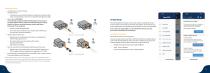
Mounting Sensors 1. Connect Sensor A to Sensor B using the M8 sensor wire a. The M8 sensor wire is directional (Sensor A accepts 6-pin, Sensor B accepts 4-pin), ensure the labels on the wire are connected to the right sensor body 2. Hard Fastening (OPTIONAL) This is optional, using the provided VHB will keep the sensors secured if properly applied. However, if preferred, and depending on mounting location, the sensors can be hard fastened using the steps below. Skip to step 3 if only using VHB. a. Use the provided drilling templates Once a maximum cutting height is set, the Yield Monitor will...
Open the catalog to page 9
4. Confirm the combine is on flat, level ground and the sensor is securely mounted, then press “Start1 5. Using the direction the combine is facing as “forward,” follow the prompts to orient the sensors: 6. Follow the same steps for Sensor B, selecting the relevant label and connector directions using the same criteria as Sensor A. 7. Sensor orientation is now complete, if successful you will see the following screen. Press “Save” to save and return to the main screen. For example, in the image above, Sensor A is mounted with label facing Right, and connectors facing backward. Sensor B is mounted...
Open the catalog to page 10
This stage will calibrate the Header Height Sensor and establish a max cutting height. You may need to repeat this step if you change headers. For example, switching from a platform header to a corn head, the max cut height will need to be re-calibrated. A tape measure is required for this step. 1. Select Header Calibration from the main menu 2. Follow the instructions in the app and lower the header until it just touches the ground. Do not push the header into the ground as this will affect the accuracy of the readings. 3. Press “Next” once the header is just touching the ground 4. Raise the...
Open the catalog to page 11
• FarmTRX mobile app will not let the orientation process complete • Incorrect label/connector direction has been selected in the app. Repeat the process and ensure the direction of the sensor label and connectors are properly chosen. • Combine is on uneven surface and there is too much pitch/roll. • The sensor body does not have one axis parallel to the wheel axle. • Area is not counting in the mobile app while actively harvesting • Max harvest height threshold was set too low. If the header is lifted above the max harvesting height threshold established during the header calibration process,...
Open the catalog to page 12All FarmTRX catalogs and technical brochures
 2025 Product Catalogue
11 Pages
 Yield Monitor Pro Info Sheet
2 Pages