- Company
- Products
- Catalogs
- News & Trends
- Exhibitions
Moisture Sensor Installation Guide
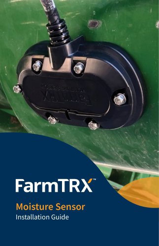
Moisture Sensor Installation Guide
The Moisture Sensor is an extension of the FarmTRX Yield Monitoring system, designed to provide real-time and average grain moisture readings during harvest. It is installed at the base of the clean grain elevator on the lower door. The sensor calculates moisture content by measuring capacitance as grain moves through the elevator, with results displayed in the FarmTRX Mobile App and uploaded to the Web App for processing.
The system includes a Moisture Sensor, stainless steel flange, enclosure, paper cutting template, a 65 mm hole-saw, and mounting hardware such as screws, locknuts, and washers.
The sensor should be installed slightly off-center on the lower door, ideally between the 6:30-7:00 o'clock position, to receive maximum grain flow and minimize debris accumulation. The wiring harness should be oriented towards the door hinge to avoid interference.
Installation requires a paper cutting template, center punch, 65 mm hole-saw, 8 mm socket, angle grinder with cut-off wheel blade, and a Phillips screwdriver.
1. Remove the lower door and position the cutting template.
2. Mark drilling locations with a center punch.
3. Drill pilot holes and use the hole-saw to create openings.
4. Optionally, use a plasma cutter or angle grinder to clear the opening.
5. Secure the sensor and flange with screws and locknuts.
6. Attach the enclosure with Nyloc nuts and washers.
7. Connect the wiring harness to the Yield Monitor Sensor Interconnect.
Installation is complete. For further guidance, refer to the FarmTRX Mobile App Guide or Quick Start Guide.
Catalog excerpts

Moisture Sensor Installation Guide
Open the catalog to page 1
Components Overview 1. Moisture Sensor • Stainless Steel Flange 2. Paper Cutting Template • 6-32 Flat Head Screw (6) • 6-32 Locknut with Spring-Lock Washer (6) • 6-32 Nylon Insert Locknut (6) How It Works The Moisture Sensor expands the FarmTRX Yield Monitoring system to provide live and average grain moisture readings during harvest. The sensor installs at the base of the clean grain elevator on the lower door. Moisture content is calculated by taking capacitance readings from grain as it moves through the elevator. Results display in the FarmTRX Mobile App and data is uploaded to the Web App...
Open the catalog to page 3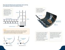
Please take the following into consideration when selecting the installation location of the Moisture Sensor: The Sensor should be slightly off from the centerline of the lower door (approximately centered between the 6:30-7:00 o’clock position). The sensor should be installed in a location where it will receive the greatest volume of grain flow. Grain flow Grain cross auger Place ahead of maximum wear Drag auger side Location of sensor Note: The below placement is optimal for most harvesters. However, if harvesting primarily soybeans consider placing the sensor further along the upside of the...
Open the catalog to page 4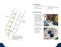
Angledelevator Tools Required • Paper Cutting Template (Included) • Center Punch • Angle Grinder with Cut-Off Wheel Blade • Phillips Screwdriver Installation Steps 1. Remove the lower door for easier handling. After carefully positioning the Moisture Sensor Cutting Template based on the guidance given in the preceding paragraphs, clean the door surface and tape the included template to the door. 2. Use a center punch to mark the cross hairs of the two hole-saw drilling locations. 3. Drill a pilot hole with the provided pilot hole drill bit. 4. Use the provided hole-saw to drill out two hole-saw...
Open the catalog to page 5
5. At this step the installer has the option to use a plasma cutter to clear the opening. If using an angle grinder cut-off wheel blade, remove the triangular pieces between the two hole-saw cuts to create a clean opening. 6. Place the Moisture Sensor against the cut opening, holding it from the outside of the hatch door. Place the stainless steel flange against the opening from the inside of the hatch door, align the bolt holes. 7. Use the supplied 6-32 Flat Head Screws and 6-32 Locknut with Spring-Lock Washers to secure the Moisture Sensor and stainless steel flange into place. 8. With the...
Open the catalog to page 6All FarmTRX catalogs and technical brochures
 2025 Product Catalogue
11 Pages
 Yield Monitor Pro Info Sheet
2 Pages