- Company
- Products
- Catalogs
- News & Trends
- Exhibitions
Yield Monitor Pro Installation Guide

Yield Monitor Pro Installation Guide
The Yield Monitor Pro system consists of an External Antenna, Yield Monitor Electronic Control Unit (ECU), Optical Sensors, and a Moisture Sensor. The antenna is mounted on the combine's cab roof and connects to the ECU, which is powered by a 12V source and linked to the sensors through harnesses. Optical sensors are installed on the clean grain elevator to measure grain volume.
The system includes the Yield Monitor ECU, External Antenna, Wiring Harnesses, Drill Guide Kit, QuickConnect Mounting Plates, and Optical Sensors. Required tools are a power drill, pliers, center punch, measuring tape, among others.
Install two optical sensors on the clean grain elevator, ensuring they are positioned high and centered on the paddles. Use the Drill Guide Kit for accurate placement, referring to the Drilling Measurements Table for specific combine models.
Install the Yield Monitor ECU in the cab, connecting it to 12V switched power using T-Splice Connectors. Mount the antenna on the cab roof's centerline for optimal mapping results. Carefully route the wiring harnesses to prevent damage.
Complete the installation by securing the sensors in the Mounting Plates and connecting them to the wiring harness. Ensure all components are securely fastened and clear of moving parts.
After installation, test the Yield Monitor and refer to the guide for interpreting and troubleshooting ECU LED indicators. For further assistance, contact the FarmTRX Support Team.
- Replace the pilot drill bit with a step drill bit and align it with the pilot hole in the elevator wall. Drill through the wall.
- Remove the drill and guide from the mounting plate. Clean the area around the hole with an alcohol swab to remove all residues.
- Attach the second mounting plate by removing its adhesive backing, inserting the drill guide, and locking it in place.
- Align the drill guide with the hole, press firmly for 15 seconds, and allow it to cure for at least five minutes before removing the guide.
- Yield: Blue solid indicates readiness, green solid indicates recording.
- GPS: Red solid for no satellites, yellow solid for 2D fix, green solid for 3D fix, and various flashing colors for different GPS states.
- CANBUS: Red solid for fault, yellow solid for warning, green solid for OK.
- Comms: Off solid for no Bluetooth connection, blue solid for connected.
- Power on the harvester to activate the Yield Monitor. Check the status LEDs for power confirmation.
- Test optical sensors by checking their status LEDs with the harvester powered on.
- Set up the FarmTRX Harvest App on a mobile device or display.
- Register for a Web App account at the appropriate FarmTRX website based on your location.
Catalog excerpts

Installation Guide
Open the catalog to page 1
This guide demonstrates the installation of a FarmTRX Yield Monitor Pro on a combine harvester. The installation process typically requires 2-4 hours and can be completed on any combine make or model with a clean grain elevator. To enhance reading, we suggest pairing this guide with the Yield Monitor QuickConnect installation video found on the FarmTRX YouTube channel.
Open the catalog to page 2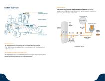
System Overview Optical Sensors: ANTENNA YIELD MONITOR ECU Two sensors install on either side of the clean grain elevator: an emitter and a receiver. A light beam is sent between the two sensors, with blocked time measuring grain volume on each paddle. External Antenna WIRING HARNESS Clean Grain Elevator OPTICAL SENSORS Optical Sensors MOISTURE SENSOR Primary Wiring Harness Interconnect Wiring Harness External Antenna: The External Antenna is mounted on the roof of the cab in the centerline of the wheelbase of the combine. The antenna connects to the Yield Monitor ECU via TNC connector Components...
Open the catalog to page 3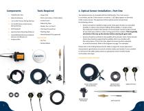
3. 3 m (10 ft) Primary Wiring Harness 4. 6 m (20 ft) Sensor Interconnect Wiring Harness 6. QuickConnect Mounting Plates (2) 7. Assembled QuickConnect Optical Sensors and Mounts (2) • Power Drill • Pliers, Vice Grips, or Side Cutters • Center Punch • Measuring Tape • Flat Head Screwdriver • Masking Tape • Round Bastard File (optional) Not Pictured: • Alcohol Wipes Two optical sensors are included with the Yield Monitor. The 2-wire sensor is an emitter, and the 3-wire sensor is a receiver. 2 LED lights appear on the body of the receiver sensor. The placement of the optical sensors should meet the...
Open the catalog to page 4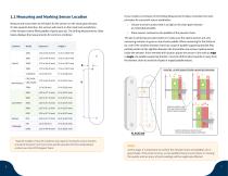
Measure and mark where to drill holes for the sensors on the clean grain elevator. On the upwards direction, the sensors will mount on the inside and outside face of the elevator (where filled paddles of grain pass by). The Drilling Measurements Table below displays the measurements for common combines: Combine Model Distance X Height Y 7120/8120 CR/CX X00, New Holland CR/CX X000 TR9X If your model is not shown in the Drilling Measurements Table, remember the main principles for successful sensor installation: 1. Choose a sensor location that is as high on the clean grain elevator as reasonably...
Open the catalog to page 5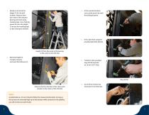
3. At the marked location, use a center punch to mark the drilling location. 1. Measure and mark the Height (Y) for the drill location. Measure from the center of the elevator bearing and mark using masking tape. Use a framing square to trace the Height (Y) across the masking tape on the clean grain elevator. 4. Drill a pilot hole using the provided pilot hole drill bit. Height (Y) from the center of the bearing to the center of the drill hole 2. With the Height (Y) marked, measure and mark the Distance (X). 5. Transfer to the provided step drill bit and drill an 18 mm (3/4”) hole. Distance (X)...
Open the catalog to page 6
1.2 Installing QuickConnect Sensors 7. IMPORTANT: Use one of the provided alcohol wipes to thoroughly clean the area around the drilled hole, ensuring all oil, grease, and residue are completely removed from the elevator face. 9. After ensuring the area around the drilled hole is clean and dry, remove the VHB backing on the adhesive side of one Mounting Plate and insert the Drill Guide into the Mounting Plate. Turn the Drill Guide clockwise to secure it in the Mounting Plate. Let the alcohol evaporate completely. If any oxidized paint is present near the hole, use a household cleaning product...
Open the catalog to page 7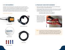
2.1 Electronic Control Unit Installation Installation of the Yield Monitor ECU in the combine cab can vary from harvester to harvester. The ECU is powered by 12V switched power and draws less than 1 Amp of current, so splicing into the radio line is acceptable. Installers are encouraged to make placement decision based on preference and first-hand knowledge of the machine. This guide will outline best-practices to ensure accurate readings. 1. Remove any headliner panels or lights needed to access 12V switched power and create a free space to install the Yield Monitor. 2. Use the supplied T-Splice...
Open the catalog to page 8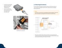
4. Connect the 12 pin Deutsch connector of the Primary Wiring Harness to the Yield Monitor ECU. For best results with mapping, the Antenna will mount at the front of the roof of the combine cab along the centerline of the combine. Refer to the diagram below for placement: 5. Mount the Yield Monitor ECU in a safe, dry, and dust free location inside the combine cab. Note: The Antenna is secured to the mounting plate using strong magnets. Take care if/ when removing the mounting plate from the Antenna to avoid pinching. MOUNT TO THE FRONT OF THE CAB ROOF 1/2 Yield Monitor ECU connection 1. If the...
Open the catalog to page 9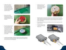
2. Prepare the surface of the cab roof by wiping the mounting location to remove dust. Once dust is removed, use the provided isopropyl alcohol wipes to clean the location. 3. Remove the red VHB backing from the Antenna mounting plate (Antenna and mounting plate remain attached). 6. Attach the Antenna wire by threading onto the main connector. Place the Antenna back on to the mounting plate. 7. Route the Antenna wire into the combine cab at a location that avoids pinching and/or chafing. The preferred entry point is the same point of access used for the Primary Wiring Harness to exit the cab....
Open the catalog to page 10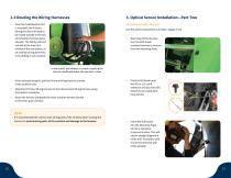
2.3 Routing the Wiring Harnesses 3. Optical Sensor Installation—Part Two 1. Once the Yield Monitor ECU is mounted, the Primary Wiring Harness will need to be routed outside of the cab and towards the clean grain elevator. The Wiring Harness can exit at the base of a window if the seal allows, at an existing wiring grommet, or by drilling a new location. Components used in this step: Use the same components as in Step 1 (pages 5-10). 1. Returning to the elevator, turn the Drill Guide counterclockwise to remove from the Mounting Plate. In this install, the harness is routed outside of the cab via...
Open the catalog to page 11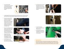
4. Turn the Drill Guide counterclockwise to remove from the Mounting Plate. Remove the pilot drill bit and replace with the step drill bit. 10. Insert both sensors into the Mounting Plates and turn clockwise to lock into place. The Receiver sensor (2 LEDs) should face outward on the elevator. Front of elevator 5. Carefully align the tip of the step drill bit with the pilot hole in the back elevator wall. Once the tip of the drill bit is engaged, drill all the way through the wall. 6. Remove the drill and Drill Guide from the Mounting Plate. Use a provided alcohol swab to thoroughly clean the...
Open the catalog to page 12All FarmTRX catalogs and technical brochures
 2025 Product Catalogue
11 Pages
 Yield Monitor Pro Info Sheet
2 Pages