

GP-750

GP-750
The document outlines the assembly process for the GP-750 Berm Flamer and associated kits. Key components include the trailer, mast, boom arm, and torch assemblies. Instructions detail securing axles, hubs, and tires, and attaching the mast and control assemblies with bolts and washers. The use of thread sealant or Teflon tape on non-flared fittings is advised for secure connections.
Before ignition, all valves must be off. The start-up involves leak checks using soapy water or a leak detector. Lighting requires adjusting the main regulator to 45-65 psi, ensuring torches stay lit in wind. Shut-down involves turning off the tank valve and letting gas burn out. Operating tips include flaming in low wind and adjusting torches after sundown for better visibility.
A checklist ensures safe operation, including valve checks, leak tests, and regulator adjustments. Warnings highlight burner temperatures post-operation and the need for well-ventilated areas to prevent burns or fatalities.
Purging new LP-Gas containers is crucial to remove contaminants like water and air. Methanol is recommended to neutralize moisture, with specific volumes based on container size. Proper purging ensures efficient transfer, prevents pressure issues, and reduces service calls.
The GP-750 and GP-1000 flamers are designed for weed management in grapevine berms and orchards, reducing herbicide use and costs. Flaming is effective year-round, with techniques for summer and winter. The alley attachment allows comprehensive weed control in one pass.
Never Purge with Liquid: Avoid purging with liquid propane as it chills the container and leaves moisture, removing less than 50% of air.
Vacuum Pre-Purged Domestic Tanks: Ensure tamper-evident seals on valves are intact before filling. If violated, re-purge according to NPGA Safety Bulletin #133-89 (a). Improper purging can cause pressure issues and odorant fade.
Vacuum Verification Process: Use a vacuum pressure gauge to verify vacuum presence. Re-purge if standards are not met.
Methanol Injection Process: Inject methanol before filling with LP-Gas using a low-pressure hose. Use at least one pint of anhydrous methanol per 100 gallons of water capacity.
LP-Gas Injection Process: After methanol injection, inject LPG into the vessel. The amount varies with vessel volume.
Filling Process: Fill the container normally after LPG injection.
Questions & Troubleshooting:
Installation Problems: Contact Flame Engineering for installation issues.
Operation Problems: Follow troubleshooting guidelines before contacting support. Ensure tanks are new, clean, and purged. Perform Methanol Injection Process before filling.
Troubleshooting Tips:
- Flame Out: Check battery connections and fuel strainer. Ensure Methanol Injection Process was performed.
- Low Flame: Check and clean torch orifices. Confirm Methanol Injection Process completion.
- No Fuel to Torches: Check solenoid connections and ensure valves are clear. Clean and lubricate solenoid components if necessary.
Catalog excerpts

GPK-454 Berm Flamer Kit GP-010 Alley Flamer Attachment Assembly and Operating Instructions
Open the catalog to page 1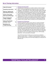
Table Of Contents Assembly Instructions 2-6 Start-up, Lighting and Operating Instructions 7 Check List for Daily Start Up and Warnings 8 Proper Purging Of LP-Gas Container 9 Vacuum Pre-Purged Domestic Tanks 10 Background Information Grapevine berm flaming is an excellent method of weed management. The first recorded flaming of grapevine berms occurred in Michigan in 1963 (NGPA 35), which also included a study of flaming blueberries and strawberries. The GP 750 and GP 1000 were originally designed for flaming grapevine berms but have been adapted for use in fruit and nut orchards....
Open the catalog to page 2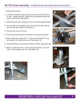
GP-750 Trailer Assembly – for GPK-454 Kits, Start at Mast Assembly Instructions 1. Slide axle into frame. 2. Locktite (or similar locking compound) set-screw into divot hole on axle – tighten securely. Tighten second setscrew directly into axle (no divot hole). See picture 1. 3. Slide hubs onto axle, making sure hub is securely against flange. 4. Place washer on and tighten axle nut and secure with cotter pin (be sure hub spins freely). See picture 2. 5. Tap dust cap onto end of hub. 6. Place tires onto hubs with valve stems to the outside and bolt. 7. Bolt on trailer jack using 3/8” x 1” bolts...
Open the catalog to page 3
GP-750 and GPK-454 – Mast Assembly Use thread sealant or Teflon® tape on all non-flared fittings. (Refer to picture 1 for steps 1 through 3) 1. Assemble brass tee (1A) onto bottom of nipple bracket (1B). 2. Assemble left and right solenoid/by-pass assemblies (1C) into right and left cross outlets – assemble so that the Ushaped hoses will face forward. 3. Assemble control head (1D) (regulator and gauge control assembly) to top of nipple – assemble so top elbow points toward the rear of unit. (Refer to picture 2 for steps 4 through 6) 4. Assemble mast onto trailer using 3/8” x 1” bolts with flat...
Open the catalog to page 4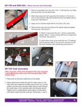
GP-750 and GPK-454 – Boom Arm and Torch Assembly 1. Bolt arm assemblies onto mast with 7/16” x 3” bolt and lock-nut. Make sure set screws (1A) are facing back. 2. Slide break-away torch arm assembly (2A) (marked L & R) into the arms so the spring pin (2B) faces toward the back and tighten the set screw (2C). See picture 2. 3. Adjust arms to desired height with the 3/4” bolts in the mast. 4. Place torches onto torch bar. Adjust to the desired angle and tighten the set-screws. See picture 3. 5. Attach 5’ hoses with tees and 1’ hoses to solenoid/bypasses. Attach 1’ hoses coming off the tee to nipples...
Open the catalog to page 5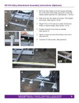
GP-010 Alley Attachment Assembly Instructions (Optional) 1 1. Bolt Torch Bar Holder (a) to the receiver brackets (b) on the back of the trailer using 3/8 x 2 bolt, flat washer spacer and lock nut. (See pictures 1, 1b &1c) 2. Slide torch bar into holder and center. Then tighten set screws. (See picture 2 & 4b) 3. Adjust 7/16 x 2 1/2” bolt (c) in center of torch bar holder to desired height. (See picture 1 & 1b) 4. Position torches on torch bar as needed. (See picture 3) 5. Tighten a nipple and brass flared fitting to each torch. (See picture 4) 6. Connect 1/2” Tee to tank. (See picture 5) FLAME...
Open the catalog to page 6
GP-010 Alley Attachment Assembly Instructions (Optional) 7. Assemble control bracket (1” tubing) into receiver bracket so it is flush at the bottom and tighten set screw (See 6a). 8. Place controls into control bracket and tighten with 3/8 bolt. (See 6b) 9. Connect 2’ hose from 1/2” Tee to the controls. (See 6C) 10. Connect hose assembly to the bottom of the control. (See 6D) 11. Connect 1’ hoses to fittings on torches.(See 6e) 12. Connect alligator clips to battery. Connect short set of wires to solenoid by the tank. Connect longer set of wires to control solenoid. 13. Test for leaks throughout...
Open the catalog to page 7
GP-750 and GPK-454 – Lighting and Operating Instructions Start-up Procedure: Turn off all valves prior to lighting torches. Turn on tank valve slowly, press red master switch, open pilot bypass valves slightly, turn on each toggle switch and leak test all LP connections from propane tank to each torch by spraying soapy water or leak detector solution (provided) on every connection. If leaks are found, turn off tank valve. Fix all leaks and begin startup procedure again until no leaks are found. SEE WARNINGS AND CHECK LIST FOR DAILY START UP ON THE FOLLOWING PAGE. Lighting Procedure: Turn on tank...
Open the catalog to page 8
Check List for Daily Start Up and Warnings WARNING! • After flaming, the burners are extremely hot and will remain so for an extended time. DO NOT make contact until sufficient cooling has occurred! • Use Extreme Caution - DO NOT Operate this unit when leaks are present. Use only in well ventilated areas. • Flames produced by this unit can reach 2,000˚ and could cause serious burns and possibly death. Fuel Tank Valve . . . . . . . . . . . . . . . . . . . . . . . . . . . . . . . . . . . . . . . Pilot Valve(s) . . . . . . . . . . . . . . . . . . . . . . . . . . . . . . . . . . . . . . . . . Regulator(s)...
Open the catalog to page 9
Proper Purging Of LP-Gas Container The Importance of Purging A very important step which must not be overlooked by LP-Gas distributors is the importance of properly purging new LP-Gas containers. Attention to this important procedure will promote customer satisfaction and greatly reduce service calls on new installations. Consider the following: • Both ASME and DOT specifications require hydrostatic testing of vessels after fabrication. This ally done with water. • Before charging with propane, the vessel will contain the normal amount of air. Both Water and Air are Contaminants They seriously...
Open the catalog to page 10
Proper Purging Of LP-Gas Container – Continued Never Purge With Liquid The wrong way of course is the easiest way. Never purge a container with liquid propane. To do so causes the liquid to flash into vapor, chilling the container, and condensing any moisture vapor on the walls where it remains while the pressure is being blown down. Additionally, less than 50% or as little as 25% of the air will be removed by this easy but wrong method. Vacuum Pre-Purged Domestic Tanks Read This Before Initial LP-Gas Filling of a Vacuum Pre-Purged Domestic Tank This new container has been vacuum purged of air...
Open the catalog to page 11All Flame Engineering, Inc. catalogs and technical brochures
 Propane Flare Literature
2 Pages
 Row Crop flamer literature
8 Pages
 GF-2011 Instruction Manual
7 Pages
 Poultry Instruction Manual
15 Pages
 Product Catalog
48 Pages
 GP-1000
13 Pages
 Roofing Catalog
20 Pages


