700
1 /12Pages

700
1 /12Pages
Catalog excerpts

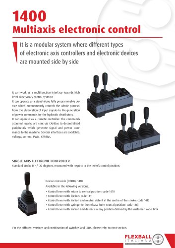
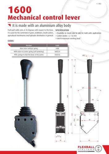
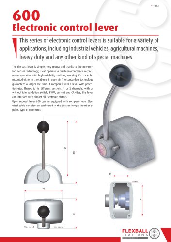
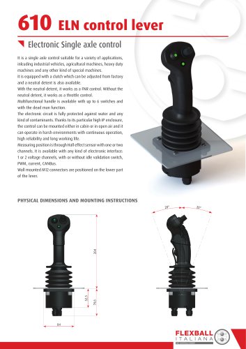
Electronic joystick Joystick series 700 combines proportional electric outputs with switches, rockers and push button. The above functions can be implemented on many different types of handles. Electrical outputs are full programmable for voltage, current, PWM and CANBus. The electronic circuit is fully protected against water and any kind of contaminants. Thanks to its particular enclosure, IP67 is guaranteed for the whole electronic circuits and environmental contamination is minimized. Measuring position is through Hall effect sensors which guarantee a precise proportional control in the whole working area with programmable reaction time for any kind of movement of the joystick’s lever. Programming via PC guarantees full flexibility in the setting of the interface profiles. Its strong structure guarantees long life operation also in case of misused conditions. The joystick is available in the versions: axis • single dual axis • dual axis (simple) full range movements • dual axis with with limited crossed movements • Single axis Dual axis with orthogonal crossed movements Dual axis with movements limited on circle boundary Dual axis with full range movements It can be configured either for top or for bottom mounting; the base mechanism, combined with specific accessories produces different joystick versions: With simple knob, without push-button With ergonomic handle, with push-buttons Top mounting Bottom mounting Top mounting Bottom mounting Base mechanism
Open the catalog to page 1
DIMENSIONS & CONFIGURATIONS Joystick with simple knob, without push-button 20° Round knob Ogival knob Bottom mounting
Open the catalog to page 2
JOYSTICK WITH ERGONOMIC HANDLE Handle type 1725 Bottom mounting FLEXBALL I T A L I A N A WR CONTROLS GROUP
Open the catalog to page 3
SPECIFICATION ELECTRICAL SPECIFICATION MECHANICAL AND GENERAL SPECIFICATION Life Hall effect Operating temperature Supply voltage Maximum input current Output voltage range 0.5 : 5V (with 2.5V in neutral position) Force to come out of centre Output current range (PWM option) Electric signals Galvanically insulated Resolution and update rate Max static load on X axis (190 mm from the rotation point) Correlation in case of 2 signals Better than 1% in the whole joystick range Max static load on Y axis (190 mm from the rotation point) Max static load on Z axis CONNECTOR PINOUT Electronic connector...
Open the catalog to page 4
SPECIAL CUSTOM PROJECTS PUSH BUTTONS CODING SYSTEM FOR ELECTRONIC JOYSTICK The code is composed of 10 digits which correspond to the following: D define the product and the joystick version: DDD = 710 single axis DDD = 720 dual axis with orthogonal crossed movements DDD = 730 dual axis with movements limited on circle boundary DDD = 740 dual axis with full range movements J defines the type of mounting: defines the type of signal: defines the type of handle (for complete description of handles refer to Chapter 7 of the Industrial Catalogue): K = 0 without handle K = 1 simple knob, round...
Open the catalog to page 5
THE JOYSTICK PROGRAMMER With this PCtool you define the correlations between the lever and the output signals. The two axis are completely independent; for each axis it is possible to define: the dead band around neutral detent signal profiles for north-south axis and respectively for east-west axis. Points which define the transfer function are: starting point after dead band zone value at medium travel end of travel ramp-up time (in ms) If the electronic joystick is connected to the PC, through the Joystick Programmer you can verify the results of your programming and eventually change the...
Open the catalog to page 6
VOLTAGE There are available 4 analogue and 4 digital signals. The analogue signal is fully programmable within the range 0-5 V and can represent: 1. either a half stroke (from centre of axis to one of the poles) 2. or a full stroke from one pole to its opposite (from e.g. South to North pole or for West to East pole). In case 1, there is only one analogue signal per each half stroke. In case 2, are available two voltage signals per every full stroke. From programming it is possible to keep the programming of the 2 axis completely independent or to make setting of axis WE (West -East) equal to...
Open the catalog to page 7
PWM There are available 4 PWM and 4 digital signals. Each PWM signal is fully programmable within the range 0-100% and represents the half stroke from centre of axis to the pole. The 4 digital signals detect the Out of centre position. Dead band position is fully programmable as previously described. Each out of centre position signal can generate a current of 500 mA and its profile is according to the drawing here below.
Open the catalog to page 8
FLEXBALL I T A L I A N A WR CONTROLS GROUP
Open the catalog to page 9
From here you have full programming access. In the red frame are depicted the parameters and function for the general setting of the communication. Parameter/function From 125 Kbit/s to 1 Mbit/s Accuracy of position signal of axis X and Y From 100 to 10.000 bit with the possibility to invert the signal Analogue input (for e.g. potentiometer, max 2) From 100 to 10.000 bit with the possibility to invert the signal Switches or digital input (max 8) Momentary – Toggle – Negate – Hand on (for only switch 1) Analog and digital signals come from the potentiometers, pushbuttons, switches, capacitive...
Open the catalog to page 10
Communication is via messages of 8 bytes. Each byte is freely configurable. Here beside are reported some of the possible information that can be stored in each byte. For the communication between the joystick and the other devices of the CANBus network you have available as standard 3 frames: TX1, TX2 and RX1. Tx1 = transmission frame (main frame) Tx2 = transmission frame; it is a second further frame Rx = receive frame, mainly used to control from remote (switch on/off) the LEDs on the knob FLEXBALL I T A L I A N A WR CONTROLS GROUP
Open the catalog to page 11
APPLICATION EXAMPLES Stand alone solution The joystick can directly command the proportional valves of an hydraulic distributor. There 8 PWM signals: 4 signals are proportional to the joystick movements 4 signal are generated on the handle via proportional rollers. Decentralized solution The commands go from the joysticks to a Power Distribution Unit via a digital signal (CANBus). The Decentralized Power Unit generates the commands to the hydraulic distributor valves (power PWM signals). The distance between the joystick and the Decentralized Power Unit can be of any length, giving full flexibility...
Open the catalog to page 12All Flexball Italiana catalogs and technical brochures
 460
4602 Pages
 415
4152 Pages
 410
4102 Pages
 400
4002 Pages
 ETC
ETC8 Pages
 1068
10682 Pages
 930
9302 Pages
 920
9202 Pages
 901
9018 Pages
 561
5614 Pages
 103
1034 Pages
 E95
E958 Pages
 2900
29006 Pages
 2800
28004 Pages
 2500
25006 Pages
 2000
20002 Pages
 1600
16002 Pages
 1500
15006 Pages
 1010
10102 Pages
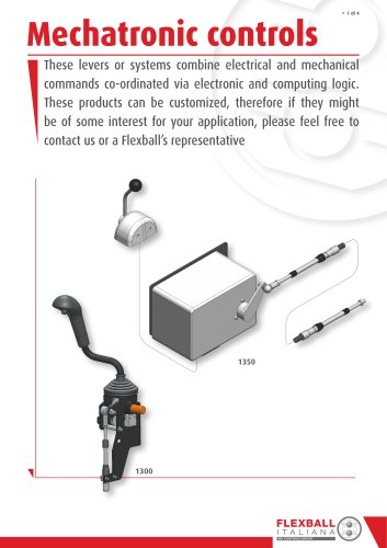 Mechatronic controls
4 Pages
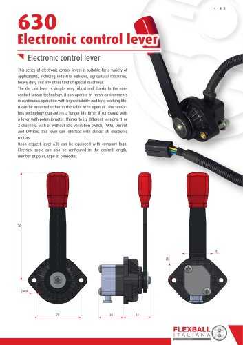 630 Electronic control lever
2 Pages
 600 Electronic control lever
2 Pages
 610 ELN control lever
2 Pages
 1280
12802 Pages
 1270
12702 Pages
 1260 and 1262
2 Pages
 1252
12522 Pages
 1240
12404 Pages
 1230
12302 Pages
 1220
12202 Pages
 1200
12002 Pages
 Industrial products
161 Pages