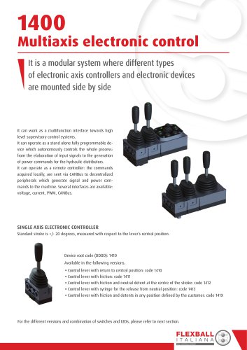
E95

E95
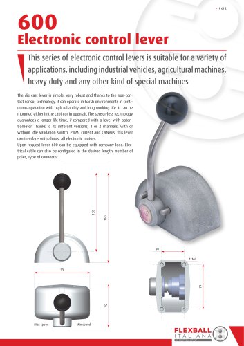
- Compatible with push-pull or Flexball cables.
- Mounting positions: side or top.
- Maximum stroke: 85 mm.
- Maximum working load: 1000 N.
- Lever ratio: 7.3:1.
- Electrical signaling via micro-switch or inductive sensor.
Catalog excerpts
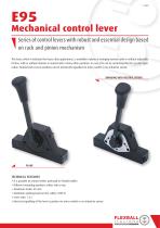
Mechanical control lever Series of control levers with robust and essential design based on rack and pinion mechanism This lever, which is indicated for heavy duty applications, is available in plane or swinging version, with or without adjustable friction, with or without detents in neutral and in many other positions. In case, E95 can be customized for the specific application. Neutral and reverse positions can be electrically signalled via micro-switch or via inductive sensor. SWINGING WITH NEUTRAL DETENT TECHNICAL FEATURES is possible to connect either push-pull or Flexball cables • ItDifferent positions: either side or top • Maximummounting 85 mm • Maximum stroke: load (on the cable): 1000 N • Lever ratio:working 7.3:1 • Electrical signalling of the lever’s position via micro-switch or via inductive sensor •
Open the catalog to page 1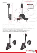
E95 MECHANICAL CONTROL LEVER > 2 di 8 E95 SWINGING WITH NEUTRAL DETENT When the lever is in the central position, the pin is inside the hole of the tempered plate and the lever is safety locked. To disengage the lever, the operator must push the lever outward in order to exit the pin from the hole. When the control lever is in neutral position, the pin on the lever is forced to enter the hole on the mask (detail A) by a spring mounted inside the lever mechanism. The lever is then locked in neutral position. To disengage the lever, it is sufficient to push the lever outwards forcing the pin outside...
Open the catalog to page 2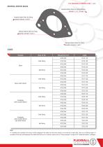
E95 MECHANICAL CONTROL LEVER > 3 di 8 NEUTRAL DETENT MASK Neutral detent hole for fixing position scheme 1, 2, 9, 10 and 11 Neutral detent hole for fixing position scheme 6 and 8 Neutral detent hole for fixing position scheme 3 and 4 Neutral detent hole for fixing position scheme 5 and 7 CODES Version Side fixing Plane with friction Top fixing Side fixing Swinging with neutral detent Top fixing Side fixing Swinging with neutral detent and with friction Top fixing Note: “X” identifies the assembly of the lever and the outgoing of the cable from the lever (which can be from left or right side)....
Open the catalog to page 3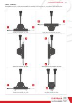
E95 MECHANICAL CONTROL LEVER > 4 di 8 FIXING EXAMPLES The numbers reported on each picture identify the assembly of the lever and the connection of cable onto the lever. Straight lever assembly, side fixing Upside-down lever assembly, side fixing Vertical lever assembly, side fixing Vertical mirrored lever assembly, side fixing 10 11 Straight lever assembly, top fixing Twin lever assembly, top fixing FLEXBALL I T A L I A N A WR CONTROLS GROUP
Open the catalog to page 4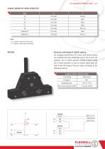
E95 MECHANICAL CONTROL LEVER > 5 di 8 CABLES WHICH FIT WITH LEVER E95 Type “A” specifies cable lever side thread “F” specifies cable engine side thread Reverse and neutral switch option On swinging control lever E95 series with neutral detent are available both the neutral (N) and/or the reverse (R) switches. The N switch operates around N detent while the R switch operates as soon as neutral signal goes off, then in the full range of reverse stroke, according to the following scheme. N AND R SWITCH SPECIFICATION Functioning Operating temp Max current (resistive load) Blue Neutral Blue Reverse...
Open the catalog to page 5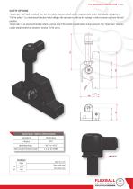
E95 MECHANICAL CONTROL LEVER > 6 di 8 SAFETY OPTIONS “Dead man” and “pull to unlock” are the two safety features which can be implemented, either individually or together. “Pull to unlock” is a mechanical function which obliges the operator to pull up the syringe in order to move out from Neutral position. “Dead man” is an electrical function which is active only if the switch or push button is kept pressed. The “dead man” function can be implemented on whatever version of E95 series. “DEAD MAN” SWITCH SPECIFICATION Functioning Operating temp Max current (resistive load) Black Vcc 12V Blue Dead...
Open the catalog to page 6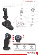
E95 MECHANICAL CONTROL LEVER > 7 di 8 HANDLE OPTION Both plane and swinging control E95 series can mount handle type 1705, 1725 and 1730. The handle represented in the drawing (1725) can be equipped up to 4 front switches + 1 rear “dead man” switch. For more detailed information about the handle type, switches, cabling, refer to chapter 7. PUSH-BUTTONS POSITION AND SPECIFICATION 5 R PUSH-BUTTONS SPECIFICATION Reference Operating temp Max current (resistive load)
Open the catalog to page 7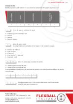
E95 MECHANICAL CONTROL LEVER > 8 di 8 CODING SYSTEM SPECIAL CUSTOM PROJECTS PUSH BUTTONS The following suffix must be added to the basic code of the standard lever E95 (page 42, at previous page). defines the type and combination of signals: S = 0 without any switch (standard version) S = 1 Neutral S = 2 Reverse S = 3 Neutral + Reverse defines the type of handle (for complete description of handles refer to Chapter 7 of the Industrial Catalogue): K = 0 standard (no switches) K = 1 “pull to unlock” K = 2 “dead man” K = 3 “pull to unlock” + “dead man” K = 4 ergonomic handle define the...
Open the catalog to page 8All Flexball Italiana catalogs and technical brochures
 460
4602 Pages
 415
4152 Pages
 410
4102 Pages
 400
4002 Pages
 ETC
ETC8 Pages
 1068
10682 Pages
 930
9302 Pages
 920
9202 Pages
 901
9018 Pages
 561
5614 Pages
 103
1034 Pages
 2900
29006 Pages
 2800
28004 Pages
 2500
25006 Pages
 2000
20002 Pages
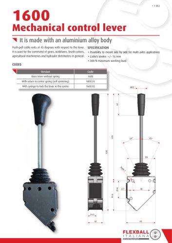 1600
16002 Pages
 1500
15006 Pages
 1010
10102 Pages
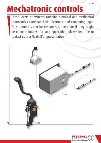 Mechatronic controls
4 Pages
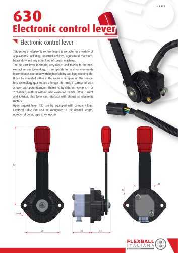 630 Electronic control lever
2 Pages
 600 Electronic control lever
2 Pages
 610 ELN control lever
2 Pages
 1280
12802 Pages
 1270
12702 Pages
 1260 and 1262
2 Pages
 1252
12522 Pages
 1240
12404 Pages
 700
70012 Pages
 1230
12302 Pages
 1220
12202 Pages
 1200
12002 Pages
 Industrial products
161 Pages