- Catalogs
- Fluence Bioengineering
- Dimmer User Manual
Dimmer User Manual

Dimmer User Manual
The Fluence Dimmer is designed to control up to 50 lighting fixtures over a maximum of 200 feet of signal wire using a 0-10V or PWM signal. It ensures uniform light intensity for crops. Exceeding 200 feet may weaken the signal, reducing the number of fixtures that can be dimmed. For longer distances, consult an electrician or Fluence support. The dimmer is not a timer for photoperiod control; use a switch or AC power timer for that purpose.
- Mounting: Use screws and drywall anchors or zip-ties to mount the dimmer near the fixture, avoiding wet areas and high humidity environments.
- Signal Type Setting: The dimmer is preset to 0-10V. For PWM, adjust the switch marked “PWM 0-10V.”
- Power Connection: Insert the 12V barrel connector into the dimmer's AC port. If using a combined power and dimming cable, the dimmer draws power from the fixture.
- Dimming Signal Connection: Connect the dimming cable to the dimmer and fixture's power supply.
- Adjusting Light Intensity: Use the up/down buttons to set light intensity (0-100%). A backup battery preserves settings for up to 24 hours during power outages.
- Changing Dimming Leads: To use custom wires, replace the supplied dimming cable by loosening set-screws and inserting new leads.
- Install away from wet environments and ensure hands are dry before use.
- Avoid installation in areas with over 80% humidity.
- If fixtures reach peak brightness below 50% intensity, adjust the 10V/PWM setting.
- Some fixtures may hum when dimmed.
- Different fixture models may power off at varying intensity levels.
- If unplugged and the battery is depleted, SPYDR fixtures will have zero intensity, while VYPR fixtures will default to 10% intensity.
- 0-10V Dimming: Voltage: 0-10V +/- .1V, Source/Sink: 40mA DC
- PWM Dimming: Signal: 0-100% +/- 1%, Source/Sink: 40mA DC
- Backup Battery: LiPo 600mA (Fully Charged)
- 12V AC Charger: Input: 120-240VAC 50/60Hz, Output: 12V at 1A
This product includes a 1-year warranty. For more details, visit: Fluence Warranty
Catalog excerpts

Dimmer User Manual
Open the catalog to page 1
OVERVIEW The Fluence Dimmer can dim up to 50 fixtures over a total of 200 feet of signal wire via a 0-10V or PWM signal to provide uniform control of light intensity delivered to your crops. Extending the signal wire more than 200 feet will weaken the signal strength and may reduce the total number of fixtures that can be dimmed. If more than 200 feet of total signal wire is needed, please consult an electrician or contact a Fluence representative at [email protected]. Please note: The Fluence Dimmer is meant to control the overall light intensity of your Fluence Bioengineering...
Open the catalog to page 2
Intensity Level Intensity Control Signal Type Switch Signal Ports
Open the catalog to page 3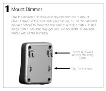
1 Mount Dimmer Use the included screws and drywall anchors to mount your Dimmer to the wall near your fixture, or use zip-ties and zip-tie anchors to mount to the side of a rack or table. Install away from areas that may get wet. Do not install in environments with 80%+ humidity. Screw & Drywall Anchor Mounting Posts Zip-Tie Anchors
Open the catalog to page 4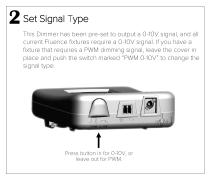
2 Set Signal Type This Dimmer has been pre-set to output a 0-10V signal, and all current Fluence fixtures require a 0-10V signal. If you have a fixture that requires a PWM dimming signal, leave the cover in place and push the switch marked “PWM 0-10V” to change the signal type. Press button in for 0-10V, or leave out for PWM
Open the catalog to page 5
3 Connect the Power Cord Insert the 12V barrel connector into the AC port on the bottom-right side of the Dimmer and twist the connector clockwise to lock into place. If your power cord is separate from the dimming signal cable, plug the AC power into the wall. If you have a combined power & dimming signal cable, the Dimmer will draw power from the fixture.
Open the catalog to page 6
4 Connect the Dimming Signal Cable Orient the dimming connector so the pin-screws are facing toward you and insert into the center dimming port on the bottom of the Dimmer. Dimming Connector
Open the catalog to page 7
If using the dual-connector cable, connect the Pushlock or Threaded connector to your fixture’s dimming port. Both connectors may be used at the same time to control separate fixtures. If using the combined power and dimming cable, insert the Pushlock connector into the Power Supply Enclosure’s dimming port to power the Dimmer and dim the fixture.
Open the catalog to page 8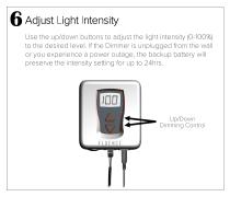
6 Adjust Light Intensity Use the up/down buttons to adjust the light intensity (0-100%) to the desired level. If the Dimmer is unplugged from the wall or you experience a power outage, the backup battery will preserve the intensity setting for up to 24hrs. Up/Down Dimming Control
Open the catalog to page 9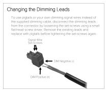
Changing the Dimming Leads To use pigtails or your own dimming signal wires instead of the supplied dimming cable, disconnect the dimming leads from the connector by loosening the set-screws using a small flat-head screw driver. Remove the existing leads and replace with pigtails before tightening the set-screws again. Signal Wire Set-Screws
Open the catalog to page 10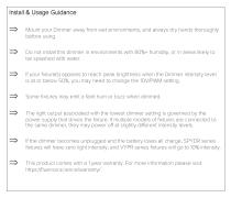
Install & Usage Guidance Mount your Dimmer away from wet environments, and always dry hands thoroughly before using. Do not install this dimmer in environments with 80%+ humidity, or in areas likely to be splashed with water. If your fixture(s) appears to reach peak brightness when the Dimmer intensity level is at or below 50%, you may need to change the 10V/PWM setting. Some fixtures may emit a faint hum or buzz when dimmed. The light output associated with the lowest dimmer setting is governed by the power supply that drives the fixture. If multiple models of fixtures are connected to the same...
Open the catalog to page 11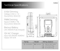
Technical Specifications 0-10V Dimming Voltage 0-10V +/- 1V Source/Sink: 40mA DC PWM Dimming Signal 0-100% +/- 1% Source/Sink: 40mA DC Backup Battery LiPo: 600mA (Fully Charged) 12V AC Charger Input 120-240VAC 50/60Hz Output: 12V at 1A
Open the catalog to page 12All Fluence Bioengineering catalogs and technical brochures
 VYPR 2x
2 Pages
 VYPR 2p
2 Pages
 RAZRx
RAZRx2 Pages
 RAZR Array
2 Pages
 SPYDR 2x
2 Pages
 SPYDRx PLUS
2 Pages
 SPYDRx
2 Pages
 SPYDR 2i
2 Pages
 SPYDR 2p
2 Pages
 RAZRx Series User Guide
10 Pages
 RAY Series
2 Pages
 VYPRx PLUS
1 Page
 VYPRx
VYPRx1 Page
 SPYDRx PLUS
1 Page
 SPYDRx
1 Page