- Catalogs
- FPM Agromehanika
- DISC MOWERS C

DISC MOWERS C
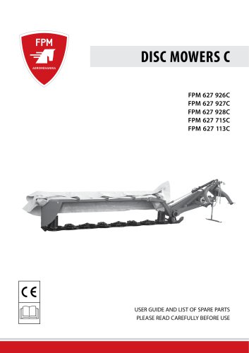
DISC MOWERS C
- General Information: Disc mowers KC are designed for harvesting grasses and forage plants, suitable for challenging conditions like wet ground or inclined surfaces.
- Technical Characteristics: Mowers have working widths from 1.6m to 3.15m, with 4 to 8 discs, requiring tractor power of 21 to 41 kW. They feature a hydraulic cutter bar suspension system and a safety mechanism.
- Identification Plaque: Essential for ordering spare parts and maintenance.
- Limited Warranty: Covers defects for 2 years, with specific conditions and exceptions.
- Warning Signals: Indicate potential dangers, categorized into four levels.
- General Recommendations: Include familiarizing with machine functions, ensuring safe distances, and adhering to transport regulations.
- Fitting the Machine: Emphasizes blocking hydraulic controls and ensuring proper linkage points.
- Using the Cardan Joint: Use prescribed joints, ensure protective parts are intact, and follow proper attachment procedures.
- Hydraulic Installations: Handle with care due to high pressure, ensuring connectors fit properly.
- Before Use: Conduct checks and ensure all safety measures are in place.
- Working with the Mower: Adjust cutter bar and cutting height as needed, and be aware of the safety device.
- Instructions for assembling components like the protective frame and swath-former.
- Guidelines for attaching the mower to a tractor, using the Cardan joint, and transporting the machine.
- Details on maintaining discs, blades, V-belts, and other components, including a schedule for regular servicing.
- Includes a compliance statement and a detailed list of parts.
- Additional advice for efficient and safe use of the mower.
1. Ensure correct connections to avoid erroneous connections that may cause injury.
2. Regularly inspect hydraulic tubes and replace them every 5 years or if damaged.
3. Address any hydraulic system leaks immediately to prevent accidents.
4. High-pressure hydraulic fluid can cause injury; seek medical attention if injured.
5. Before maintenance, ensure the machine is grounded, pressure is released, and the engine is off.
1. Turn off all power sources before maintenance.
2. Regularly check and tighten nuts and bolts.
3. Secure the machine with appropriate support when raised.
4. Use protective gear and appropriate tools when replacing parts.
5. Use only original spare parts as recommended by the manufacturer.
6. Repairs on pressurized parts should be done by trained personnel.
1. Maintain a safe distance from revolving mower discs.
2. Avoid loose clothing to prevent entanglement.
3. Ensure all protective parts are in place before use.
4. Regularly inspect and replace damaged cutting elements and protective parts.
5. After a collision, inspect the machine thoroughly before resuming work.
1. Ensure warning labels are visible and legible.
2. Labels can be ordered from the manufacturer if needed.
1. Follow specific instructions for assembling protective frames and hydraulic cylinders.
2. Ensure all components are securely fastened with the correct torque specifications.
1. Properly fit the mower to the tractor, ensuring correct alignment and secure connections.
2. Adjust the mower to maintain a 5 cm gap from the wheel tract.
3. Ensure the Cardan joint is correctly set and not operating at excessive angles.
1. Secure all moving parts and protective elements before transport.
2. Follow specific steps to prepare the mower for safe transport.
1. Perform pre-use checks to ensure all components are in good condition.
2. Operate the mower at the prescribed shaft revolutions for optimal performance.
3. Exercise caution on uneven ground and adjust the mower to minimize blade contact with foreign objects.
- Never attach the Cardan joint to the tractor output shaft with 750 or 1000 RPM.
- Remove stones, foreign objects, and hidden obstacles from the working area before starting.
- Ensure the protective canvas is in place and lowered when using the mower.
- Ensure no persons or animals are within the mower’s work area before starting.
Adjusting the Cutter Bar:
- Place the axle into the working position to release the spring and allow proper ground handling.
- Use the hydraulic cylinder to lower the cutter bar into the working position.
- Adjust the mower using tractor levers to ensure the linkage point centers are at 450 mm height.
- Ensure the cutter bar leans on the ground, the chain is tight, and the linkage points are around 400 mm from the ground.
Adjusting the Cutting Height:
- Rotate the cutter bar around the longitudinal axis by adjusting the coupling length.
- Ensure blades do not hit the ground during operation to avoid damage.
Safety Device:
- The safety device is set for normal conditions and activates upon encountering obstacles.
- Adjust the safety device spring to prevent activation under normal conditions.
Swath-former Adjustment:
- Adjust the coil spring for proper swath shape and mowed mass flow.
- Ensure the angle is close to 90° in difficult conditions.
Maintenance and Adjustments:
- Regularly check and tighten screws, nuts, and V-belts.
- Oil all grease fittings and sliding surfaces regularly.
- Change oil in the torque multiplier and cutter bar after the first 8 hours and every 200 hours thereafter.
Parking and Storing:
- Lower the mower into the horizontal position for parking.
- Clean and wash the mower before long-term storage.
- Release and refill oil, replace damaged blades, and tighten all screws.
- Store the mower in a dry, protected area.
Useful Tips:
- Adjust the carrier frame for proper cutter bar floating.
- Tighten the spring on the safety device if the mower balance slat unlocks.
- Adjust the tension chain for setting the cutter bar angle.
1. Cutting Issues: Adjustments are necessary for uneven cuts, such as modifying the cutter bar incline, increasing Cardan joint revolutions to 540 rpm, reducing tractor speed, and replacing blunted or broken blades. Ensure V-belts are properly tightened.
2. Height and Wind Adjustments: For plants cut too high, adjust the cutter bar angle. If wind affects cutting, change the mowing direction or regulate Cardan joint revolutions.
3. Wear and Ground Conditions: Use appropriate blades and reinforced discs for difficult conditions. Increase carrier frame height on wet ground to prevent earth from sticking to the cutter bar.
The document includes detailed drawings and tables listing machine parts with numbers, model references, ID numbers, labels, names, quantities, and additional specifications like dimensions and required tightening torque. It emphasizes using original spare parts approved by FPM AGROMEHANIKA to ensure proper machine functioning and performance.
When ordering spare parts, provide the product label, serial number, part ID or label, part name, quantity, and delivery details to avoid misunderstandings.
1. Linkage and Carrier Frame: Lists parts applicable to all models with specific part numbers and quantities.
2. Hydraulic Lifting System: Details parts for hydraulic components across different models.
3. Belt Carrier: Includes parts for belt systems, specifying variations for different machine models.
4. Swath-former: Lists components for swath-forming mechanisms.
5. Protective Awning: Details parts for protective structures, with variations across models.
6. Cutter Bar: Extensive list of parts for cutter bar assembly, including reinforced options and specific components like bearings, seals, and gears.
The document provides a detailed list of parts for various models of disc mowers manufactured by FPM Agromehanika. Each part is listed with its part number, model compatibility, description, quantity per machine, and specific notes. Key components include plugs, washers, locknuts, springs, bearings, screws, bushings, gears, O-rings, oil seals, bolts, and spacers. The parts are organized by group and model, indicating the specific requirements for each machine type.
Compliance Statement:
FPM Agromehanika declares that their disc mowers comply with the EU Directive 2006/42/EC for machines. The models listed include FPM 627 726, FPM 627 716, FPM 627 678, among others, with varying numbers of discs. The compliance is supported by adherence to several standards, including SRPS EN ISO 12100:2014, SRPS EN ISO 13857:2010, and others.
Standards and Safety:
The document confirms that the machines meet the relevant safety requirements of the EC directive for machines. The standards ensure the safety and operational efficiency of the disc mowers.
Contact Information:
FPM Agromehanika is located at Đorđa Simeonovića 25, 19370 Boljevac, Serbia. Contact can be made via their website or telephone numbers provided.
Catalog excerpts

USER GUIDE AND LIST OF SPARE PARTS PLEASE READ CAREFULLY BEFORE USE
Open the catalog to page 1
General information about the product 4 Meaning of the warning signals 6 Fitting the machine onto a tractor 7 Using the Cardan joint 1 2 3 Assembling the protective frame carrier 10 Assembling the internal protective sheet 11 Assembling the protective frame 12 Fitting onto a tractor 13 Working with the mower 17 Adjusting cutting height 18
Open the catalog to page 2
Discs and cutting blades 19 Controlling the blades and cutting discs 19 Oiling the grease fittings and sliding 21 Oiling the Cardan joint 21 Schedule for regular servicing and 22 9. LIST OF SPARE PARTS 25
Open the catalog to page 3
This user guide contains detailed information required for the proper use and maintenance of the product. We are asking you to read it carefully before using the product and to observe the instructions for proper functioning, maintenance, and safe use. The instructions will help you get to know all features and characteristics of the product, as well as the sequence for performing all necessary operation during use. Failure to observe the recommendations and instruction can lead to damage to the product and to serious injury to the user and nearby persons. NOTE: FPM AGROMEHANIKA IS CONSTANTLY...
Open the catalog to page 4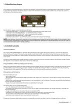
1.3 Identification plaque For the purposes of ordering spare parts, as well as for any questions concerning the proper use and maintenance of the product, it is necessary to state information from the identification plaque. In order for this information to be always easily available to you, we advise you to enter it into the blanks of the illustration below. The identification plaque contains the following information: - In the field marked with “Z” – you will find the number of certificate (document) for safety at work. - In the field marked with “MASA/WEIGHT” – you will find the product’s weight;...
Open the catalog to page 5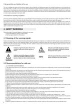
IV Responsibilities and liabilities of the user The user is obliged to respect all instructions stated in the user guide, and relating to proper use, setting, maintenance, servicing, and storing of the product, as well as to carry out all actions intended for regular maintenance and servicing of the product at an authorised service centre. In case of a problem occurring during use, they must immediately contact a distributor from which they purchased it or a nearby authorised service centre. Also, the user must give for inspection a receipt and a warranty form to the distributor or an authorised...
Open the catalog to page 6
1. Before every attaching or detaching of the machine from a tractor, block hydraulic controls in order to prevent any unwanted rising or lowering. 2. While attaching the machine onto a tractor, make sure that the tractor linkage points correspond to the machine linkage points. 3. The area around the linkage points is very dangerous, so be particularly careful. 4. While using external hydraulic controls, do not stand between the tractor and the machine. 5. Block lateral motion of joining levers of the tractor during transport. 6. While transporting the machine, fix the hydraulic controls of the...
Open the catalog to page 7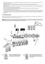
6. Before each use of the mower, check the condition of the cutting elements (blades, discs). In case they are damaged or overly-worn, replace them immediately. 7. When replacing worn-out or damaged blades, always replace them in pairs in order to avoid unbalancing the discs. 8. Regularly check the mower’s protective canvas and other protective parts. Immediately replace the worn-out or damaged canvas and parts with new ones. 9. When the Cardan joint power take-off is turned off, the mower’s moving parts will continue to rotate for some time. Wait for the moving parts to come to a halt before...
Open the catalog to page 8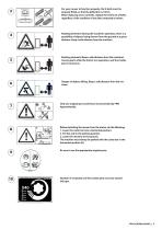
For your mower to function properly, the V-belts must be properly fitted, so that the deflection is 10mm. When replacing worn-out belts, replace the entire set of belts, regardless of the condition of one belt compared to others. Rotating elements! During the machine’s operation, there is a possibility of objects being thrown from the ground at a great distance. Keep a safe distance from the machine. Rotating elements! Keep a safe distance from the machine’s moving parts while the tractor is in operation, and the Cardan joint is turned on. Danger of objects falling. Keep a safe distance from...
Open the catalog to page 9
3. ASSEMBLY Safety warnings of a potential danger are indicated in two ways: In order to facilitate the transport of the mower, certain parts and assemblies are disassembled. Depending on the target market, the extent of disassembling may vary. In order to assemble the mower properly and prepare it for use, do the following: 3.1 Assembling the protective frame carrier and hydraulic cylinder Fasten the carrier frame (D) (figure 11) to the four-screw multiplier (M12x35) (E) as shown in figure 11 (tighten the screws with the torque of 14 daNm). NOTE: FOR MOWERS FPM 627.928/715/113, DO NOT TIGHTEN...
Open the catalog to page 10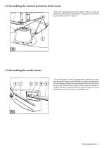
3.2 Assembling the internal protective sheet metal - Fasten the internal protective sheet metal (J) with four screws (H) (M10x20), four flat washers (dimensions 10x21x2) and four self-locking nuts (M10), as shown in figure 15. - The swath-former is fitted by fastening the swath-former carrier onto the spot (O) using a screw (M12x80), coil spring, special washer, and self-locking nut (figure 16). Pay attention that the nut fits in such a way that the swath-former remains mobile. Fasten the wooden lever (R) to the sheet metal (U) using the connective panel (Y), screw (W)(M8x50), and two self-locking...
Open the catalog to page 11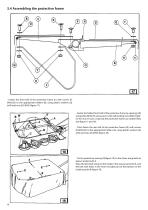
3.4 Assembling the protective frame - Fasten the front half of the protective frame (C) with screws (F) (M10x25) to the appropriate holders (B), using plastic washers (Q) (ø10) and nuts (O) (M10) (figure 17). - Fasten the folded front half of the protective frame to openings (N) using bolts (M10x75) and secure it with self-locking nuts (M10). Tighten the nuts in such a way that the protective frame can rotate freely (see figure 17 and 18). - Then fasten the rear half of the protective frame (W) with screws (F)(M10x25) to the appropriate holders (A), using plastic washers (Q) (ø10) and nuts (O)...
Open the catalog to page 12All FPM Agromehanika catalogs and technical brochures
 OFFSET/IN LINE MULCHER
2 Pages
 HAY TEDDER
2 Pages
 POWER HARROWS
2 Pages
 GARDENING
2 Pages
 FPM Catalogue
104 Pages
 BELT HAY RAKE
24 Pages
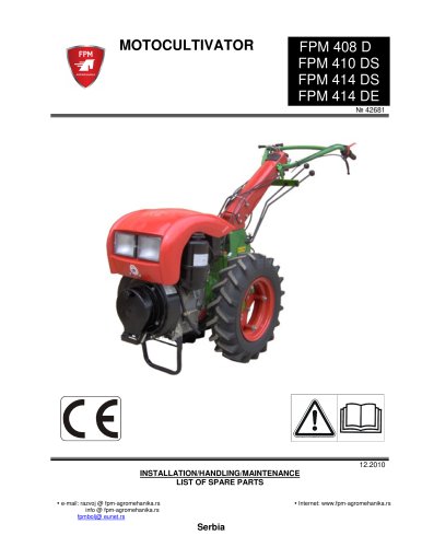 MOTOCULTIVATOR
66 Pages
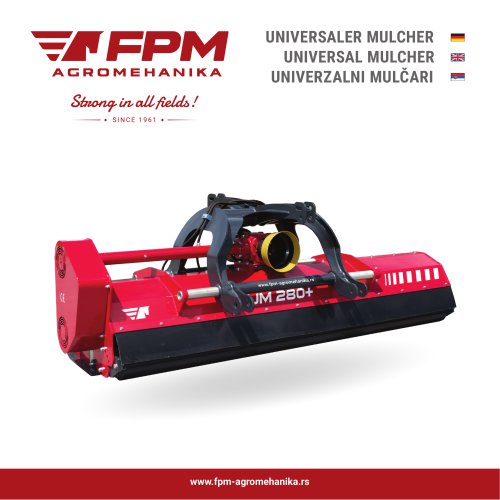 UNIVERSAL MULCHER
2 Pages