
Catalog excerpts

Harleman Manufacturing -Vibratory Drill- Model lO Harleman Manufacturing 117 South St. James El Dorado Springs, MO 64744 (office)417-876-3011 (fax)417-876-3091
Open the catalog to page 1
Harleman MSg. 117 S. St. James El Dorado Springs, MO 64744 417-876*3011 ■ (tax): 417-876-3091 ronharleman@hotmail.com www.harlemanmfg.com B&I 2- ALL major credit cards accepted
Open the catalog to page 3
A This is the safety alert symbol. When you see this symbol on your equipment or in this manual, be alert to the potential for personal injury or injury to others. This symbol means to take notice. Following this symbol is useful and important information. Before using your new machine, you and all other operators should completely read through this manual. Failure to fully understand how to operate this machine and take safety precautions could lead to serious injury and death. These signs should remain on the machine always, DO NOT remove. If the signs ever become lost or damaged they...
Open the catalog to page 4
Read through entire manual Always keep the manual in a safe and easily accessible place. Check bolts for tightness periodically. Make sure to replace all missing or damaged decals. Do not make unauthorized modifications to machine which could decrease its stability and life or cause injury and possibly death. We also encourage you to only use authorized replacement parts from Harleman Mfg. which w ere made specifically for this machine. If there is any part of this guide you do not understand feel w elcome to call our shop any time during normal business hours Mon-Fri 8am-4:30pm. The number...
Open the catalog to page 5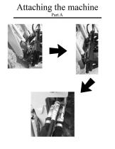
Attaching the machine Part A
Open the catalog to page 6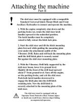
The skid steer must be equipped with a compatible Standard Universal Quick Mount Hitch and Front Auxiliary Hydraulics to connect and operate the machine. 1. With the engine completely shut down and the parking brake set, rotate the skid steer latch handles upward to the unlatched position. The latch handles must be completely raised to fully retract the hitch lock pins. 2. Start the skid steer and tilt the hitch mounting plate forward while guiding the mounting plate crest under the attachment saddle of the Vibratory Drill. Raise and roll back the mounting plate until the drill hitch plate...
Open the catalog to page 7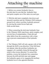
1. Before you connect hydraulic lines to the skid steer be sure that the hydraulic lines and quick couplers are of the same size and type. 2. With the skid steer completely shut down and secured in position and the Vibratory Drill resting at ground level, relieve auxiliary hydraulic pressure by moving the control levers back and forth several times. 3. When connecting the skid steer hydraulic lines to the Vibratory Drill, keep hoses, quick couplers, and swivels free of contamination. Clean dirt and other debris from the connections with a clean rag to prevent contamination of the...
Open the catalog to page 8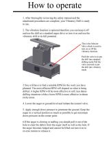
I. After thoroughly reviewing the safety manual and the attachment procedures are complete, your Vibratory Drill is ready to use. 3.You will have to find a suitable RPM for the work you have planned. The most efficient RPM will depend on what is being drilled. A higher RPM will be most effective in soft, less dense drilling situations while a lower RPM is more effective in dense rocky areas. 4. Lower the auger to ground level and initiate the control valve. 5. Apply enough down pressure to penetrate the ground. Keep the auger in a vertical position as much as possible to get maximum down...
Open the catalog to page 9
Y Properly Cleaning and Storing your new machine is critical 0 to maintaining its appearance and ensuring years of service. 1. Thoroughly clean all debris off the Vibratory Drill to prevent damage. 2. Check the Vibratory Drill for worn and damaged parts periodically. Perform repairs and make replacements immediately to prevent potential hazards. 3. Make sure to store the Vibratory Drill in a clean, dry place. 4. Keep the hydraulic hose ends from sitting in water, dirt and other contaminants. Connect the drill’s hydraulic lines together to prevent dirt and other contamination from entering...
Open the catalog to page 10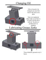
If the oil needs to be changed you must first remove the front cover plate. Since our equipment ships ready to use there is no need to fill the drive with oil. The drive is prefilled prior to shipping.
Open the catalog to page 11
Auburn Gear Engineered Drive Solutions
Open the catalog to page 12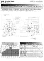
Model 200 Wheel Drives -Double Reduction GENERAL SPECIFICATIONS Max. intermittent output torque1 200,000 lb-in (22,600 N-m) Approximate weight: 385 lbs (175 kg) Max. input speed2: 5,000 RPM Oil capacity: 110 oz (3,250 cc) ' Depending on the duty cycle and the nature of the application, a normal continuous output torque of 1/3 to 1/2 of the maximum intermittent should yield satisfactory Power Wheel life. Customer testing and application analysis is strongly recommended 2 For N and Bolt-on senes brakes, please contact Auburn Gear for input speeds above 4.000 rpm for application analysis....
Open the catalog to page 13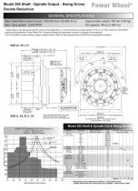
Power Wheel® Model 200 Shaft - Spindle Output - Swing Drives Double ReductionGENERAL SPECIFICATIONS Max. intermittent output torque1 200,000 lb-in (22,600 N-m) Approximate weight: 300 lbs (136 kg) Max. input speed2: 5,000 RPM Oil capacity: 96 oz (2,850 cc) ' Depending on the duly cycle and the nature of the application, a normal continuous output torque of 1/3 to 1/2 of the maximum intermittent should yield satisfactory Power Wheel life Customer testing and application analysis is strongly recommended. 7 For N and Bolt-on senes brakes, please contact Auburn Gear for input speeds above...
Open the catalog to page 14
• Enhanced gear technology provides more power density without increasing external dimensions • Precision computer-aided bearing setting allows for optimal bearing life • Optimized carrier designs provide for greater resistance to shock and torsional loads, hence increasing gear box life • Increased bearing capacity allows for additional radial load Auburn Gearf Engineered Drive Solutions 400 East Auburn Drive Auburn. Indiana 46706-3499 • USA ph: 260.925.3200 fx. 260.925.4725 e-mail: powerwheel@auburngear.com web: http://www.auburngear.com
Open the catalog to page 15All Harlemanglobal catalogs and technical brochures
-
HAR-BB72 & HAR-BB78
12 Pages
-
HP970
12 Pages
-
HP970MR42
12 Pages
-
Root Grapple
8 Pages
-
GROUND FORCE BRUSH BEAVER
12 Pages


