- Catalogs
- Headsight, Inc.
- grain_header_manual-agco_draper
grain_header_manual-agco_draper

grain_header_manual-agco_draper
- Safety Precautions: Ensure all safety measures are followed, such as turning off the combine and securing the header before installation.
- Assembling Terrace Sensors: Align sensor holes with the mounting bracket, secure with hardware, and adjust the leveling bolt.
- Mounting Terrace Sensors: Remove the crop divider tip, route extension wires, and mount the sensor assembly carefully to avoid pinching wires.
- Standard Sensors (Undermount): Determine mounting locations, install sensors, and ensure proper spacing and clearance from moving parts.
- Routing Wiring: Proper wiring routing is crucial. Use the harness length table to select appropriate wiring and ensure slack and clearance from moving parts.
- Install Sensor Wands and Tether Cables: Attach wands to sensors and secure tether cables to prevent catching on moving parts.
- Install Controller: Mount the controller near the single point using provided brackets and hardware.
- Sensor Adjustment: Adjust voltage and down pressure for both terrace and standard sensors by loosening screws and adjusting bolts as needed.
Catalog excerpts

GRAIN HEADER MANUAL: AGCO DRAPER 09030402b HEADSIGHT HARVESTING SOLUTIONS
Open the catalog to page 1
About Headsight Headsight Contact Info Headsight, Inc. 4845 3B Road Bremen, IN 46506 Phone: 574-546-5022 Fax: 574-546-5760 Email: [email protected] Web: www.headsight.com Technical Assistance Phone: 574-220-5511 About this Manual How to use this manual The instructions in this manual are in the order that they should be completed for new installations. Complete all applicable instructions in each section before proceeding. Note that some sections are labeled to indicate they only apply to certain machines or applications. An index is available in the front of the manual to help find technical...
Open the catalog to page 3
About Headsighti About this Manuali Installation1 Assembling Terrace Sensors (If Equipped)2 Mounting Terrace Sensors (If Equipped)3 Standard Sensors (Undermount)4 Routing Wiring6 Harness Length Table6 Removing Wires for Tight Access6 Install Terrace Sensor Wiring (If Equipped)7 Install Standard Sensor Wiring8 Outer Sensor Wire Routing9 Inner Sensor Wire Routing9 Install Sensor Wands and Tether Cables10 Install Controller11 Settings12 Sensor Adjustment12 Terrace Sensor12 Standard Sensor13 Parts14 Terrace Sensor14 Standard Sensor15 STATEMENT OF LIMITED WARRANTY 16
Open the catalog to page 4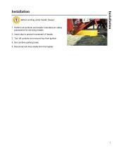
Before working under header always: 1. Perform all combine and header manufacturer safety precautions for servicing header. 2. Insert stop to prevent movement of header. 3. Turn off combine and remove key from ignition. 4. Set combine parking brake. 5. Disconnect all drive shafts from the header.
Open the catalog to page 5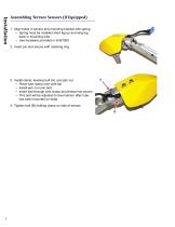
Assembling Terrace Sensors (If Equipped) 1. Align holes in sensor and mounting bracket with spring. • Spring must be installed short leg up and long leg back in mounting tube • Use hardware provided in kit B7000 2. Insert pin and secure with retaining ring. 3. Install clamp, leveling bolt (A), and jam nut. • Place wire clamp over wire tail • Install jam nut onto bolt • Insert bolt through wire clamp and thread into sensor • This bolt will be adjusted to level sensor after tube has been mounted on head 4. Tighten bolt (B) holding clamp on side of sen
Open the catalog to page 6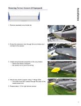
Mounting Terrace Sensors (If Equipped) 1. Remove standard crop divider tip. 2. Route the extension wire through the end divider and connect to the sensor. 3. Install sensor/bracket assembly to the crop divider. • Reuse the factory hardware • Be careful not to pinch the wiring 4. Mount poly wand to sensor using 1" flange bolts. • The bolts must NOT extend through the back of the metal sensor arm 5. Repeat steps 1-5 for right terrace sensor.
Open the catalog to page 7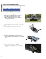
Standard Sensors (Undermount) 1. Determine sensor mounting location. 2. Mount outer sensors first, mounting out as far as possible (if not equipped with terrace option.) • Mount all inner sensors as evenly spaced as possible across the head 3. Remove large cover from sensor, retain hardware and cover. 4. Remove bolt holding wiring clamp inside sensor. 5. Mount sensor to brackets with hardware provided. • Leave hardware finger tight for ease of wire routing later 6. Determine mounting location on skid plate. • Make sure that draper belt will not hit the sensor bracket
Open the catalog to page 8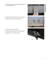
7. Hold the bracket on the bottom side of the skid and mark the hole locations. 8. Drill four holes through skid plate to mount bracket. 9. Enlarge holes in poly to recess bolt heads. 10. Mount sensor bracket assembly. 11. Mount poly wand to sensor using 1" flange bolts. 12. Repeat steps 1-11 for other sensors.
Open the catalog to page 9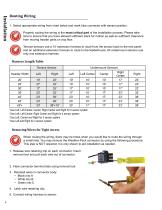
Routing Wiring 1. Select appropriate wiring from chart below and mark blue connector with sensor position. Properly routing the wiring is the most critical part of the installation process. Please take time to ensure that you have allowed sufficient slack for motion as well as sufficient clearance from moving header parts or crop flow. Terrace sensors use a 10' extension harness to route from the sensor back to the end panel and an additional extension harness to route to the feederhouse. All undermount sensors use only one extension harness. Harness Length Table *Use Left, Left Center, Center,...
Open the catalog to page 10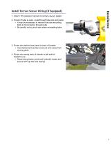
1. Attach 10' extension harness to terrace sensor pigtail. 2. If back of tube is open, route through tube into end panel. • It may be necessary to remove the tube mounting bolts to fit connector through tube • Be careful not to pinch wire when reinstalling bolts Install Terrace Sensor Wiring (If Equipped) 3. Route wire behind end panel to back of header. • Use clamps and zip ties to secure wire away from moving parts 4. Route wire along back of header to left side of feederhouse. • Route along factory wire and hydraulic hoses and secure with zip ties and clam
Open the catalog to page 11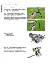
Install Standard Sensor Wiring 1. Select appropriate length harness using table above. 2. Install protective conduit on wiring coming from sensor. • Use 6ft conduit for outer sensors • Use 3ft conduit for inner sensors 3. To aid installing conduit on sensor wiring without damaging wire insulation, tape a wrench big enough to open conduit wider than wire diameter. 4. Insert box end of wrench into conduit using it as a guide to slide conduit over wire. Remove wrench and repeat for all other standard mount sensors. 5. Attach wire to bracket. • Clamp at location A • Zip tie at locations B 6. Route...
Open the catalog to page 12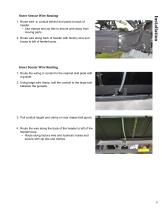
1. Route wire in conduit behind end panel to back of header. • Use clamps and zip ties to secure wire away from moving parts 2. Route wire along back of header with factory wire and hoses to left of feederhouse. Outer Sensor Wire Routing Inner Sensor Wire Routing 1. Route the wiring in conduit to the nearest skid plate with a gusset. 2. Using large wire clamp, bolt the conduit to the large bolt between the gussets. 3. Pull conduit taught and clamp on rear draper belt guard. 4. Route the wire along the back of the header to left of the feederhouse. • Route along factory wire and hydraulic hoses...
Open the catalog to page 13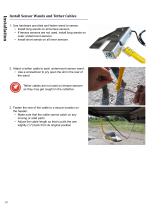
Install Sensor Wands and Tether Cables 1. Use hardware provided and fasten wand to sensor. • Install long wands on all terrace sensors • If terrace sensors are not used, install long wands on outer undermount sensors • Install short wands on all inner sensors 2. Attach a tether cable to each undermount sensor wand. • Use a screwdriver to pry open the slit in the rear of the wand Tether cables are not used on terrace sensors as they may get caught in the cutterbar. 3. Fasten the rear of the cable to a secure location on the header. • Make sure that the cable cannot catch on any moving or solid...
Open the catalog to page 14All Headsight, Inc. catalogs and technical brochures
 HEADER CONTROL FOR GRAIN
8 Pages


