Basic Electronics

Basic Electronics
The document aims to provide a basic understanding of electronics concepts and familiarize readers with key terminology.
Ohm’s Law is defined as Voltage (V) = Resistance (Ohms) x Current (Amps), represented by the formula V = R x I.
The document compares hydraulic systems to electrical systems, highlighting components such as hoses and tubing versus board traces and wires, and pressure versus voltages.
Inputs are categorized into Switch-to-Battery, Switch-to-Ground, Analog, Frequency, and RTD. Each type is explained with examples such as joysticks for analog inputs and engine speeds for frequency inputs.
Outputs include Sinking, Sourcing, Analog, PWM, Digital, and Servo. Each type is described with its function and application, such as PWM for varying voltage output.
The document explains additional terms like Debounce Time, Frequency Gauges, Resistance Gauges, and Numbering Systems, including Binary and Hexadecimal systems.
Discusses the role of CAN Controllers in microcontrollers, memory types like Flash, RAM, and EEPROM, and their functions in storing and processing data.
Catalog excerpts
Basic Electronics Basic Electronics
Open the catalog to page 2
Training Objectives Provide knowledge / basic understanding of electronics concepts Familiarize / provide definitions of key terminology
Open the catalog to page 3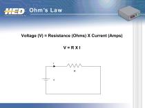
Voltage (V) = Resistance (Ohms) X Current (Amps) V=RXI
Open the catalog to page 4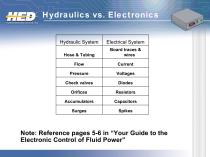
Hydraulics vs. Electronics Hydraulic System Electrical System Hose & Tubing Board traces & wires Check valves Note: Reference pages 5-6 in “Your Guide to the Electronic Control of Fluid Power
Open the catalog to page 5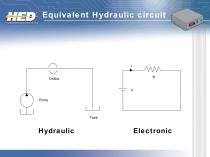
Equivalent Hydraulic circuit
Open the catalog to page 6
Switch-to-Battery Switch-to-Ground Analog Freque
Open the catalog to page 7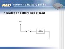
Switch on battery side of load
Open the catalog to page 8
Switch on Ground side of load
Open the catalog to page 9
Analog Also known as a/d, analog to digital, voltage to digital Provides controller with a voltage – Voltage is between 0 to the defined upper voltage range (example 0 – 5 VDC) – Steps are based on resolution Resolutions – 8 bit, range is from 0 – 255 – 10 bit, range is from 0 – 1023 – 12 bit, range is from 0 – 4095 Common use: joysticks, foot pedals,
Open the catalog to page 10
Common analog input Output ranges can vary Example: 10% joystick (supplied with 5VDC) – Center is 2.5VDC – Maximum output is 3VDC – Minimum output is 2
Open the catalog to page 11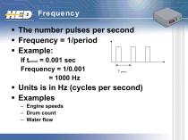
The number pulses per second Frequency = 1/period Example: If tperiod = 0.001 sec Frequency = 1/0.001 = 1000 Hz Units is in Hz (cycles per second) Examples – Engine speeds – Drum count – Water f
Open the catalog to page 12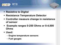
Resistive to Digital Resistance Temperature Detector Controller measure change in resistance of sensor Example ranges 0-250 Ohms or 0-4,000 Ohms Used: – Engine temperature sensors – Fuel gauge
Open the catalog to page 13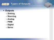
Sinking Sourcing Analog PWM Digi
Open the catalog to page 14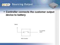
Sourcing Output Controller connects the customer output device to battery
Open the catalog to page 15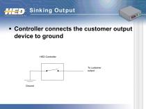
Sinking Output Controller connects the customer output device to ground
Open the catalog to page 16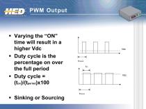
Varying the “ON” time will result in a higher Vdc Duty cycle is the percentage on over the full period Duty cycle = (ton)/(tperiod)x100
Open the catalog to page 17
Is a simple on or off output. Can be sourcing or sinking If On and sourcing, supplying battery from the controller
Open the catalog to page 18
Allows for controlling a motor/valve in two direction (bi-direction) Eg: H-bridge Battery + + Motor Switch 4 Switch 2
Open the catalog to page 19
Other terms Debounce time Frequency gauges Resistance gauges Numbering Systems Truth tables Microcontroller
Open the catalog to page 20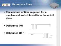
Debounce Time The amount of time required for a mechanical switch to settle in the on/off state Debounce ON Debounce OFF
Open the catalog to page 21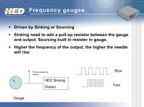
Frequency gauges Driven by Sinking or Sourcing Sinking need to add a pull-up resistor between the gauge and output. Sourcing built in resister in gauge. Higher the frequency of the output, the higher the needle will rise Pull-up resistor to battery HED Sinking Output Gauge
Open the catalog to page 22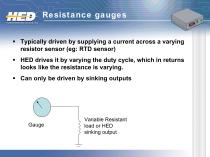
Resistance gauges Typically driven by supplying a current across a varying resistor sensor (eg: RTD sensor) HED drives it by varying the duty cycle, which in returns looks like the resistance is varying. Can only be driven by sinking outputs Variable Resistant load or HED sinking output
Open the catalog to page 23
Numbering Systems Decimal = base 10 Binary = base 2 Hex = base 16
Open the catalog to page 24
What is sent down the CAN bus Example: 1001 = 9 2 Single digit is called a bit 4 bits equal a nibble – Nibble
Open the catalog to page 25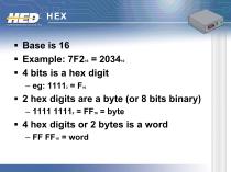
Base is 16 Example: 7F2 = 2034 4 bits is a hex digit 16 2 hex digits are a byte (or 8 bits binary) – 1111 11112 = FF16 = byte 4 hex digits or 2 bytes is a word – FF FF16 = w
Open the catalog to page 26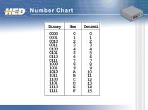
Number Chart
Open the catalog to page 27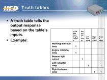
Truth tables A truth table tells the output response based on the table’s inputs. Example: J1939 Msg from Engine stoppe d Warning indicator lamp Left turn signal Right turn signal Engine indicator lamp Beacon light output Left indicator lamp Right indicator lamp
Open the catalog to page 28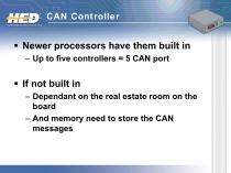
Newer processors have them built in – Up to five controllers = 5 CAN port If not built in – Dependant on the real estate room on the board – And memory need to store the CAN messa
Open the catalog to page 30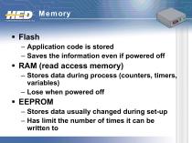
Flash – Application code is stored – Saves the information even if powered off RAM (read access memory) – Stores data during process (counters, timers, variables) – Lose when powered off EEPROM – Stores data usually changed during set-up – Has limit the number of times it can be w
Open the catalog to page 31
Training Objectives Provide knowledge / basic understanding of electronics concepts Familiarize / provide definitions of key terminology
Open the catalog to page 32All HED Inc. catalogs and technical brochures
 HED Application
12 Pages
 CAN and Multiplexing
30 Pages