CAN and Multiplexing

CAN and Multiplexing
CAN, or Controller Area Network, is a serial bus communication system designed for real-time control applications. It facilitates communication across a pair of wires to various nodes or microprocessors without using addresses, relying instead on identifiers. Every node on the CAN bus can see every message, which is transmitted as a differential signal over two wires.
Developed by Robert Bosch GmbH in the mid-1980s, the first CAN chips were produced by Intel and Philips in 1987. CAN was introduced to automation in 1992, with the first car implementation in a Mercedes Benz. Key milestones include the release of SAE J1939 in 1994 and ISO 11898 in 1995.
CAN is widely used in various industries, including automotive, packaging equipment, medical systems, marine controls, and more. Specific examples include military vehicles, agricultural machinery, and construction equipment.
The communication rate for J1939 is 250Kbits/second, with a maximum of 2Mbits/second for CAN. It supports 11 or 29-bit identifiers, with CANOpen using only 11-bit identifiers. The system is backward compatible, and 120-ohm terminating resistors are used.
CAN operates across several layers, including the Physical, Data Link, and Application layers, which together form part of the OSI model. The Physical Layer involves hardware for node-to-node communication, while the Data Link Layer handles data frames and error detection. The Application Layer provides end-user services and supports various high-level protocols like J1939, CANOpen, and DeviceNet.
Error detection mechanisms include bit monitoring, stuff errors, cyclic redundancy checks (CRC), form errors, and acknowledge errors. These ensure reliable communication by flagging discrepancies and violations in message formats.
CAN messages consist of an 11 or 29-bit identifier, data frames, and fields for start, data length, CRC, acknowledgment, and end frame. An example J1939 message includes parameters like engine temperature, with specific data lengths and resolutions.
Organizations such as SAE, CiA, and ODVA utilize CAN for its industry-proven reliability, cost savings, and diagnostic capabilities. CAN effectively handles bit collision detection and offers robust EMI/RFI resistance.
For more details, resources are available at websites like www.sae.org, www.can-cia.org, and www.hedonline.com.
Catalog excerpts

Training Objectives Summarize CAN multiplexing history & origins Explain CAN technology Explain CAN benefits
Open the catalog to page 2
CAN stands for Controller Area Network Definition: Serial bus communication for real-time control application.
Open the catalog to page 3
What do we mean by CAN? CAN is a communication across a pair of wires to different nodes/microprocessors Messages on the CAN bus do not carry addresses, only identifiers Every node sees every message on the CAN bus CAN is a differential signal on two wires
Open the catalog to page 4
CAN (Controller Area Network) was created by Robert Bosch Gmbh in mid 1980’s Version 1.2 had 11 bit identifiers Version 2.0B released Sept. 1991 provided for 11 bit and 29 bit identifiers Base patent still held by Bosch
Open the catalog to page 5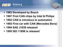
1983 Developed by Bosch 1987 First CAN chips by Intel & Philips 1992 CAN is introduce to automation 1992 First car with CAN (Mercedes Benz) 1994 SAE J1939 released 1995 ISO 11898 is released
Open the catalog to page 6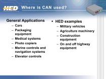
Where is CAN used? General Applications – Cars – Packaging equipment – Medical systems – Photo copiers – Marine controls and navigation systems – Elevator controls HED examples – Military vehicles – Agriculture machinery – Construction equipment – On and off
Open the catalog to page 8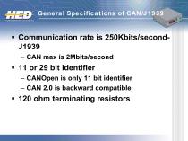
11 or 29 bit identifier – CANOpen is only 11 bit identifier – CAN 2.0 is backward compatible
Open the catalog to page 10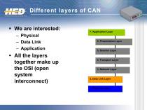
Different layers of CAN We are interested: – Physical – Data Link – Application All the layers together make up the OSI (open system interconnect) 2. Data Link Layer
Open the catalog to page 11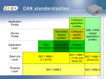
CAN standardization CANopen application profiles Application Profile Device Profile DeviceNet device profiles Application Layer SAE J1939 -based application profiles Data Link Layer Physical Layer CANopen device profiles
Open the catalog to page 12
Consist of the hardware needed to communicate from node to node – Physical/driver chip • Converts 1’s & 0’s to differential voltage – Twisted pair of wire – C
Open the catalog to page 13
The layer that defines data, remote, error, and overload frames. Layer that turns the data into raw bits Also part of the error detection
Open the catalog to page 16
Error Detection Bit Monitoring – Any node automatically monitors and compares the actual bit level on the bus with the level that it transmitted. If the two are not the same, a bit error is flagged. Stuff Error – If five consecutive identical bit levels have been transmitted, the transmitter will automatically inject (stuff) a bit of opposite polarity into the bit stream. The receive node will automatically de-stuff
Open the catalog to page 17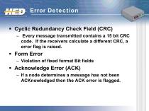
Error Detection Cyclic Redundancy Check Field (CRC) – Every message transmitted contains a 15 bit CRC code. If the receivers calculate a different CRC, a error flag is raised. Form Error – Violation of fixed format Bit fields Acknowledge Error (ACK) – If a node determines a message has not been ACKnowledged then the ACK error is flagg
Open the catalog to page 18
The application layer is the communication layer of the OSI. – Performs common end user services – HED application cod
Open the catalog to page 19
High Language Protocols J1939 – Diesel engines, busses, fire trucks, cranes, etc… CAN Kingdom CANOpen – Used in Europe especially Germany DeviceNet – Used in USA and Asia for PLC controllers
Open the catalog to page 20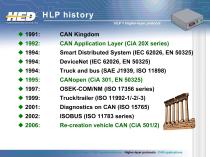
HLP history HLP = Higher-layer protocol CAN Application Layer (CiA 20X series) Smart Distributed System (IEC 62026, EN 50325) CAN introduction - CAN protocols - CAN physical layer - CAN implementations - Higher-layer protocols - CAN applications
Open the catalog to page 21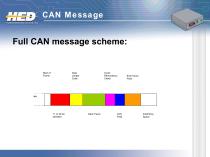
Full CAN message scheme: Data Length Code Cyclic Redundancy Check Data Frame Interframe Space
Open the catalog to page 22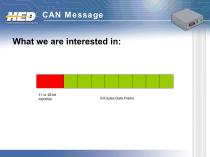
0-8 bytes Data Frame
Open the catalog to page 23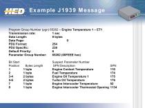
Program Group Number (pgn) 65262 – Engine Temperature 1 – ET1 Transmission rate: 1 sec Data Length: 8 bytes Data Page: 0 PDU Format: 254 PDU Specific: 238 Default Priority: 6 Parameter Group Number: 65262 (00FEEE hex) Bit Start Position 1 2 3-4 5-6 7 8 Bytes Length 1 byte 1 byte 2 bytes 2 bytes 1 byte 1 byte Suspect Parameter Number SPN Description Engine Coolant Temperature Fuel Temperature Engine Oil Temperature 1 Turbo Oil Temperature Engine Intercooler Temperature Engine Intercooler Thermostat Opening
Open the catalog to page 24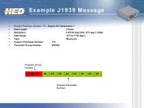
Example J1939 Message Suspect Parameter Number 175 – Engine Oil Temperature 1 Data Length: 2 bytes Resolution: 0.03125 deg C/bit, -273 deg C offset Data Range -273 to 1735 deg C Type: Measured Suspect Parameter Number: 175 Parameter Group Number: [65262] Program Group Number 00 FEE 00 Suspect Parameter Number
Open the catalog to page 25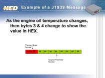
As the engine oil temperature changes, then bytes 3 & 4 change to show the value in HEX. Program Group Number 00 FEE 00 Suspect Parameter Number
Open the catalog to page 26
SAE (Society of Automobile Engineers) CiA (CAN in Automation) ODVA (DeviceNet)
Open the catalog to page 27
Industry proven Bit collision detection and handling Cost saving Diagnostics for multiple module systems EMI/RFI
Open the catalog to page 28
Want to learn more? Check these websites for more information – www.sae.org – www.can-cia.org – www.hedonline.com HED papers – Large Scale Applications of J-193
Open the catalog to page 29
Training Objectives Summarize CAN multiplexing history & origins Explain CAN technology Explain CAN benefits
Open the catalog to page 30All HED Inc. catalogs and technical brochures
 HED Application
12 Pages
 Basic Electronics
32 Pages