- Catalogs
- I.S.E. Srl
- MCE MAN
MCE MAN

MCE MAN
The MC-E controller by Irritrol is a solid-state irrigation controller designed for commercial and contractor applications. It supports eight independent programs and is compatible with previous MC Plus B cabinets and wiring connections.
The controller includes a 32-character dot matrix LCD, timing mechanism quick release, active station indicator display, function dial, flow alarm indicator LED, master valve active indicator LED, and power supply indicator LED.
Cabinet Installation: Install in a weather-protected location using wood screws. For larger units, additional screws are required. Lockable steel pedestals are available for free-standing applications.
Electrical Conduit Installation: Install a 1/2” NPT threaded conduit for power wires and a 2” conduit adapter for station valve wiring, following local electrical codes.
Control Wires Installation: Use 18 AWG multi-wire cable for runs up to 1000’. Connect wires to valve solenoids and secure connections with wire nuts and waterproofing.
Set time/date format, current date and time, security password, and master valve settings per station.
Assign stations and runtimes, set program start times, station delay times, looping start times, and watering day schedules. Adjust water budget and review or erase programs as needed.
Includes rain off, semi-auto, and manual operations. Remote control and flow sensor options are available separately.
Detailed specifications and electromagnetic compatibility information are provided at the end of the document.
Comply with national and local electrical codes. Use 14-AWG insulated solid copper wires for connections. Ensure power is disconnected before proceeding.
The controller isolates stations with short circuits, displaying a "Fuse Alarm" for the affected station.
Rain Sensor: Designed for a normally closed rain sensor. If no sensor is connected, a wire jumper must be present.
Start Sensor: Designed for a normally open sensor, triggering Program 1 when activated.
Adjusts the MC-E Blue’s global water budget according to weather conditions.
The master valve is enabled by default for all stations. It can be disabled through the setup menu if not required.
Secures the controller with a four-digit password to prevent unauthorized access.
Programs require stations with assigned runtimes and specific activation times. Avoid using midnight as a start time.
Stations can be added, modified, or deleted from programs. Runtimes can be set in various time formats.
Includes even days, skip days, and odd/even days schedules. Adjust the global water budget to conserve water.
Review program parameters without modification. Options to erase single programs or reset the controller are available.
Activates all stations for a specified duration to test functionality.
Includes various operational modes and remote control capabilities.
Monitors and manages water flow, reducing the risk of flood damage.
Enable flow sensing and set parameters for operation. Adjust flow delay time as needed.
Cabinet dimensions, input/output voltage, temperature, and humidity specifications are detailed.
Complies with FCC regulations.
Contact details for the U.S.A., Europe, and Australia are provided.
Catalog excerpts
RELEASED Version Installation Instructions and Programming Guide
Open the catalog to page 1
Thank capab MC-E desig Introduction - - - - - - - - - - - - - - - - - - - - - - - - - - - - - - - - - - - - - - - - - - - - - - - - - - - - - - -Pg. 3 Parts Diagram - - - - - - - - - - - - - - - - - - - - - - - - - - - - - - - - - - - - - - - - - - - - - - - - - - - - -Pg. 3 Cabinet Installation - - - - - - - - - - - - - - - - - - - - - - - - - - - - - - - - - - - - - - - - - - - - - - - - Pg. 4 Electrical Conduits Installation - - - - - - - - - - - - - - - - - - - - - - - - - - - - - - - - - - - - - - Pg. 4 Control Wires Installation - - - - - - - - - - - - - - - - - - - - - - - - - - - - -...
Open the catalog to page 2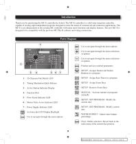
Introduction Thank you for purchasing the MC-E controller by Irritrol. The MC-E controller is a solid-state irrigation controller, capable of storing eight independent programs designed to meet the needs of commercial and contractor applications. The MC-E is an enhancement to the existing MC controller with many more functions and display features. The new MC-E is designed to be compatible with the previous MC Plus B cabinets and wiring connections. Parts Diagram - Use to navigate through the menu options - Use to navigate through the menu selections or options - Use to navigate through the menu...
Open the catalog to page 3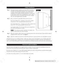
Cabinet Installation Step 1 – Selecting the proper installation site for the MC-E controller is essential to safe and reliable operation. The controller features a weather resistant cabinet designed for indoor and outdoor installation. The controller should be installed on a vertical wall or other sturdy structure near a grounded power source. Select a location that provides as much protection from direct sunlight, rain, snow and irrigation spray as possible. Step 2 – Drive a wood screw (provided) into the wall at eye level. (For Large Cabinet Unit - 18 Stations or more) Drive another wood screw...
Open the catalog to page 4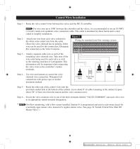
Control Wires Installation Step 1 – Route the valve control wires between the valves and the MC-E controller. For wire runs up to 1000’ between the controller and the valves, it is recommended to use an 18 AWG (1.0 mm2) multi-wire sprinkler valve connection cable. This cable is insulated for direct burial and is color coded to simplify installation. Figure 2 Step 2 – Attach one wire from each valve solenoid to Wiring for standard (non-flow sensing) system the white color-coded wire from the cable. (Since the valve solenoid has no polarity, either wire can be used for this connection.) Designate...
Open the catalog to page 5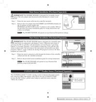
Rain Sensor Installation (Purchased Separately) IMPORTANT! The INHIBIT SENSOR is designed for a normally closed rain sensor. The wire jumper must be present at the terminals if a sensor is not connected. INHIBIT SENSOR START SENSOR VALVE VALVE MASTER COMMON COMMON VALVE Step 1 – Route the rain sensor cable into the controller terminals. Step 2 – Remove the wire jumper from the INHIBIT and SENSOR terminals for the 18 stations or more models and INHIB.SEN and SEN.COM for the 12 stations or less models. Refer to the provided rain sensor installation guide for wiring instructions and connect accordingly....
Open the catalog to page 6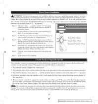
Power Source Installation WARNING: All electrical components and installation practices must meet applicable national and local electrical codes including installation by a qualified personnel. These codes may require an external junction box mounted on the cabinet and a circuit breaker in the main wiring having a contact separation of at least 0.120” in the line and neutral poles. 1 The 120 VAC power source must be turned OFF prior to servicing. The power cable used for connection to the controller must have an insulation rating of 221° F minimum. Step 1 – For power source connection, install...
Open the catalog to page 7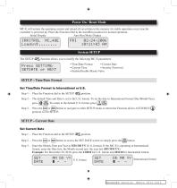
MC-E will initiate the operating system and reload all saved data in the memory for stable operation every time the controller is powered up. Place the Function Dial in the Auto/Run position for normal operation. Initial Display Auto Run Mode Display IRRITROL LoadinS . System SETUP Press SETTIME, SETDRTE or NEXT l_J The SETUP function allows you to modify the following MC-E parameters: • Time/Date Format • Current Date • Current Time • Security Password • Enable/Disable Master Valve Set Time/Date Format to International or U.S. Step 1 - Place the Function dial to the SETUP position. Step 2 -...
Open the catalog to page 8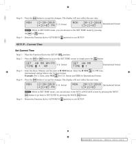
Step 4 - Press the |ehter| button to accept the changes. The display will now reflect the new date. U.S. format International format While in SET DATE mode, you can advance to the SET TIME mode by pressing Step 5 - Return the Function dial to AUTO/RUN © position to exit SETUP - Current Time Set Current Time Step 1 - Place the Function Dial to the SETUP Step 2 - Press the button to access the SET TIME screen or simply press the L,ME button. International fonnat for U.S. fonnat and 1321 for International fonnat. button to accept the changes. The display will now reflect the new time. Step 3 - Enter...
Open the catalog to page 9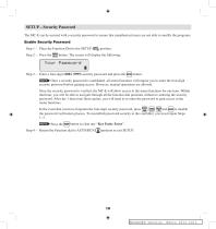
SETUP – Security Password The MC-E can be secured with a security password to ensure that unauthorized users are not able to modify the programs. Enable Security Password Step 1 – Place the Function Dial to the SETUP Step 2 – Press the button. The screen will display the following: Step 3 – Enter a four-digit (0001–9999) security password and press the Once a security password is established, all menu functions will require you to enter the four-digit security password before gaining access. However, manual operations are allowed. Once the security password is verified, the MC-E will allow access...
Open the catalog to page 10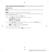
SETUP - Master Valve ON or OFF per Station Set Master Valve GEH^ As factory default, the Master valve is Enabled for all stations. The master valve will activate whenever a station is activated. tjv, position, button. The following display will be shown on the screen. If flow sensing is to be activated, all stations must be set to “MV=ON”. In situations that a station does not require the master valve to activate, use the following procedure to select the station and Disable or Enable the master valve. Step 1 - Place the Function Dial to the SETUP Step 2 - Press the buttons to select the station...
Open the catalog to page 11All I.S.E. Srl catalogs and technical brochures
 LIFE™ DC
2 Pages
 Icod Plus
2 Pages
 Electronic Tap Timer
1 Page
 Junior Plus
2 Pages
 Junior Max
2 Pages
 Rain Dial
2 Pages
 S Series
2 Pages
 200B Series
2 Pages
 700 Ultraflow Series
2 Pages
 Kwik Dial
2 Pages
 MC-E
MC-E2 Pages
 Minisat
4 Pages
 New Tap Timer
1 Page
 Remote Control Kit
2 Pages
 Total Control
2 Pages
 Landscape Irrigation Catalogue 2015
114 Pages
- Vitirover hose
- Irrigation valve
- Vitirover irrigation hose
- Vitirover plastic hose
- Impact sprinkler
- Plastic coupling
- Irrigation control system
- Plastic valve
- Vitirover threaded irrigation fitting
- Straight coupling
- Polypropylene irrigation fitting
- Threaded valve
- Plastic nozzle
- Digital irrigation control system
- Weather station
- Elbow irrigation fitting
- Vitirover male irrigation fitting
- Vitirover female irrigation fitting
- Automated sprinkler