- Catalogs
- Klingenburg GmbH
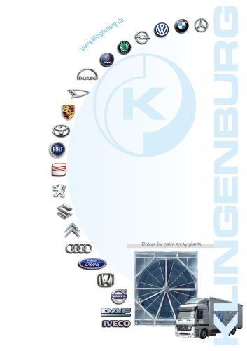
- Rotors for Paint Shops
Rotors for Paint Shops
1 /23Pages
Rotors for Paint Shops
1 /23Pages
Catalog excerpts
· Rotors for paint spray plants
Open the catalog to page 1
■ Rotor casing and bearing ■ Wheel construction and rotor matrix ■ Scavenging and sealing air/chamberair sealing
Open the catalog to page 2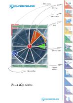
Rotor casing Rotor casing and bearing Rotor matrix Wheel construction and rotor matrix Cleaning sector Cleaning sector Scavenging and sealing air/ chamber air sealing Cleaning systems By-pass flaps Cleaning systems Electrical components Paint shop rotors · About us ·KLINGENBURG Contact
Open the catalog to page 3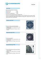
Casing Types Rotor Casings Rigid construction optionally consisting of ■ Aluminium alloy FT-RRT ■ Stainless steel FT-RRV ■ Sheet steel, hot-dip galvanised FT-RRB with internal inclined condensation tub and condensation drain. All frames can accommodate rotor wheels up to 6000 mm in size. The casing houses the rotor wheel, bearings, rotor drive, cleaning device, gasket system and integrated air sealing system. Inspection doors on one or both sides allow easy access to all components. Aluminium casing FT-RRT ■ made of corrosion-resistant aluminium alloy ■ especially suitable for use in plants with...
Open the catalog to page 4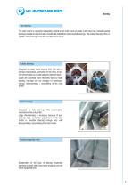
The bearings The rotor matrix is supported adjustably, outside in the rotor frame or inside in the rotor hub. Outside located bearings are able to absorb loads considerably better than inside located bearings. The outside bearings offer, in addition, the advantage to be disassembled more easily. Outside bearings Designed as pillow block bearing SNV 130 with or without relubrication, insensitive to the entry of dirt, with preservation as condensate anti-adhesive layer. Loads are absorbed more efficiently than by inside bearing; bearings can be changed (if necessary) without disassembling / assembling...
Open the catalog to page 5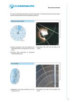
Rotor wheel construction The matrix is coiled with waved and flat, continuous wound layers. The wheel which turning at 10 rpm is able to transmit sensible and latent heat with a high degree of efficiency. Sectorally-reinforced design + Sectoral construction of the rotor segments with intermediate profiles to compensate for any forces arising + Assembing of the rotor from the centre to the outside + Extremely stable construction for particularly contaminated exhaust air Con-rod design + Stabilisation of the sectors achieved by con-rods and pressure rods + Assembling of the rotor from the outside...
Open the catalog to page 6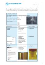
Rotor matrix The rotor profile has to be selected in consideration of the degree of soiling, required cleaning intervals as well as the required efficiency. The material should be resistant to the chemicals in the exhaust air, and where a wet paint deposition process is applied, it must also be resistant to the different types of system tank water and their Rotor profile and material grade The rotor profile is characterised by the material thickness and the wave height. Wave height_ Material thickness_ Grades (typical) Application conditions ■ high tensile strength all painting method ■ high...
Open the catalog to page 7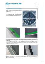
Seals Highly efficient sealing systems minimize the loss of air due to leaks. The circumferential seals are self-adjusting and permanently adapt to the rotation of the rotor wheel. Permanently fixed plastic seals or profiled sheet metal with extremely small clearance to the rotor are used as center seals. The fan arrangement "pushing exhaust air fan and succing supply air fan" requires a scavenging and sealing air system or the controlled chamber air sealing system to avoid entrained rotation and leakage of exhaust air (see chapter "controlled chamber air sealing"). Systems in which sealing is...
Open the catalog to page 8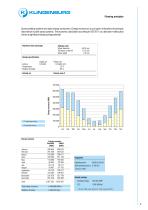
Rotational heat exchanger Enthalpy rotor Design specifications Supply air Exhaust air Airflow 120.000 120.000 m3/h Outside air Climate zone 2 □ Sensible heat recovery □ Latent heat recovery Energy recovery Energy recovery Sensible Latent Total operating hours: 8,760 h/y 7 days a week Total energy recovery: 4.469.888 kWh/a Annual savinns: * 30 EUR/MWh energy, 400 kg C0;/MWh energy (VDI 2071)
Open the catalog to page 9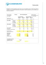
Rotor and housing are not assembled when supplied Rotor type RRT-E-A25-5250/5250-5010 Dry paint deposition Wet paint deposition Supply air Exhaust air Supply air Exhaust air Aluminium housing 0,12 mm thickness of the foil 2,5 mm wave height Face air velocity Pressure drop Pressure drop (standard density) Moisture (latent) efficiency 18 Heat recovery Altitude above sea level 0 m
Open the catalog to page 10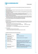
Planning principles Thefollowing principles should be observed in planning rotating heat exchangers for paint spraying systems: ■ Vertical mounting should be preferred, horizontal mounting is possible, but not recommended for systems with wet paint deposition. ■ Horizontal and vertical separation of the airflows is possible, for horizontal separation the exhaust air should be the down flow - if possible. ■ The installation surface must be level and plane, if the equipment is installed on a steel platform or a base, a baseframe all around is necessary, also sections supporting pointloads, (center...
Open the catalog to page 11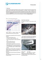
Planning principles 4. Rotor icing The high moisture content of the exhaust air causes much water to condense at the extract air side of the heat wheels of paint spraying plants with wet paint deposition. The changes of state are illustrated in the psychometric chart. It is clear from the chart that the connecting line of the entry states, the outside air and exhaust air in wet paint deposition plants intersects the saturation line at two points and lies in the mist area. As a result of this condensate forms at the rotor, which cannot be absorbed by the heating outside air/supply air. So called...
Open the catalog to page 12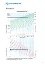
·KLINGENBURG Layout diagram Recommended operation range The design program for rotor profile A25 is most commonly used in paint spraying systems. Air flows relate to standard density of r = 1.20 kg/m³
Open the catalog to page 13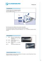
Cleaning sector The cleaning sector The double cleaning sector prevents entry of exhaust air into the supply air due to entrained rotation of exhaust air within the rotor matrix. Part of the outside air flow is deflected in order to achieve a cleaning effect. This avoids entrained rotation of exhaust air within the rotor matrix into the supply air. This purge effect is obtained due to the pressure difference Δp = p 21 - p 12 between the outside air and the extract air. Effect of the cleaning sector not warranted. Use rotor without cleaning sector. Standard cleaning sector 2 x 5 degrees required....
Open the catalog to page 14All Klingenburg GmbH catalogs and technical brochures
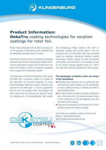
 Sorption Rotor HUgo
4 Pages
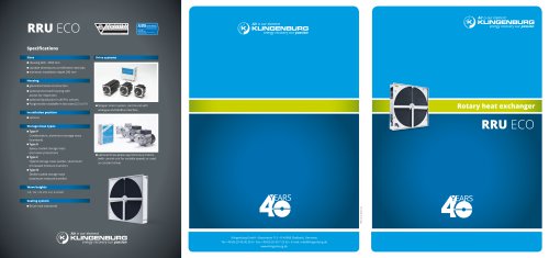
 Overview Rotary Heat Exchanger
13 Pages
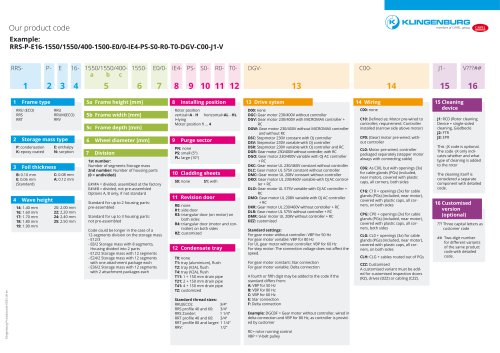 product code
1 Page
 Product Overview
11 Pages