
- Catalogs
- Köckerling GmbH & Co. KG
- Grasmaster

- Products
- Catalogs
- News & Trends
- Exhibitions
Grasmaster
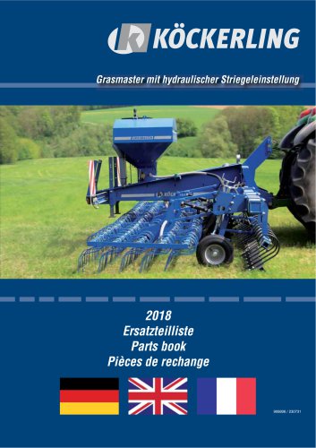
Grasmaster
Overview
This document is a comprehensive technical reference and spare parts list for the Köckerling GRASMASTER agricultural machinery. It covers mechanical, hydraulic, and electrical components, including detailed part numbers, specifications, and assembly information. The content is multilingual (German, English, French) and structured to support construction, maintenance, and repair activities.
1. Frames and Structural Components
Includes the main chassis (centre frame), side frames, parallelogram linkage, and tine frame. Key elements are bolts (M16, M6-M20), spring bushes, lockpins, washers, and hydraulic adjustment parts. These components ensure structural integrity, secure assembly, and proper frame positioning.
2. Wheels and Supports
Details depth wheels and tail wheels with their mounting brackets, bearings (ball bearings 6205 LLU), pins, washers, lynch pins, and adjustment turnbuckles. The tail wheel assembly includes a ground drive with angle gear and lubrication points, ensuring smooth operation and durability.
3. Leveler and Drag Components
Describes soil leveling tubes, adjustable brackets, U-bolts, tine elements, wear plates, and mounting plates. These parts are designed for effective soil engagement and drag functionality.
4. Drillbox and Seed Delivery
Focuses on drillbox frames, parking stands, clamps, tank cross-ties, access steps, and seed string supports. Emphasizes secure mounting and protection of seed hoses and strings to ensure accurate seed distribution and prevent spillage.
5. Lighting and Electrical Components
Includes LED position lights, warning decals, lighting cable sets with color-coded wiring (yellow, green), plugs (7-pin, 4-pin), connectors, cable clips, and protective casings. Assembly instructions for LED lighting systems (post-2017 models) are provided to ensure compliance with safety and visibility standards.
6. Hydraulic Systems
Covers hydraulic cylinders, folding mechanisms, tine frame adjustments, drill stops, seal kits, hydraulic tubes, hoses, check valves, pressure limiting valves, and quick couplings. Emphasizes the use of specified hoses and fittings, correct coupling color codes, and regular maintenance to prevent leaks and ensure reliable operation.
7. Transmission and Gear Components
Details frames, gear wheels, air baffle plates, transmission protectors, levers, chain tighteners, shafts, bearings, agitators, hose adapters, deflectors, and rollers. Regular inspection and lubrication are recommended to maintain smooth operation and reduce wear.
8. Fan Assembly
Describes inner and outer housings, protective grids, bearings, belt pulleys, belts, axles, fan wheels, protective casings, hoses, clamps, cardan shafts, and feed rollers. Protective elements must be intact to avoid damage or injury.
9. Assembly and Disassembly Instructions
References numbered illustrations (not included) for correct installation and maintenance procedures, critical for operational reliability and safety.
Critical Information and Best Practices
- Use specified bolt grades (e.g., 10.9 zk) and dimensions for mechanical strength.
- Lockpins and spring bushes are vital for secure assembly and vibration resistance.
- Maintain hydraulic seals and components to prevent leaks.
- Follow color coding and wiring instructions for lighting to ensure safety compliance.
- Inspect wear plates and tine elements regularly; replace as needed.
- Ensure protective casings and grids on fans are intact.
- Adhere strictly to assembly/disassembly guidelines to avoid damage.
Summary of Key Parameters
- Bolt sizes range from M6 to M20 with various lengths and strength grades.
- Spacer tubes and bushes have precise dimensions (e.g., 36/45/36 mm, 28/35/28 mm) for correct fitment.
- Bearings include ball bearings 6205 LLU and plain bearings GSM 28/35/28.
- Lighting cables are 4x0.75 mm in yellow and green with IP64 rated plugs.
- Hydraulic components include O-rings (125x8 mm) and seal kits tailored for cylinder maintenance.
Manufacturer and Contact Information
Landmaschinenfabrik Köckerling GmbH & Co. KG
Address: Lindenstraße 11-13, 33415 Verl, Germany
Phone: +49 5246 96080
Fax: +49 5246 960821
Website: www.koeckerling.de
Email: [email protected]
Regional support available via France SAS branch.
Conclusion
This document is an essential technical resource for the Grasmaster machinery, providing detailed parts lists, specifications, and assembly guidance. It ensures correct part usage, safety compliance, and maintenance best practices to optimize machine performance and longevity.
Catalog excerpts
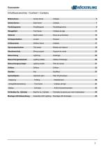
Inhaltsverzeichnis / Content / Contenu Mittelrahmen Centre frame Side frame Tine frame Depth wheel Drillbox frame Tail wheel String support Lighting cables Câbles d'éclairage Lighting holder Hydraulic plan Plan d'hydraulique Tine frame Drill stop Arrêt d'ensemencement Pochette de joints pour verin hydraulique
Open the catalog to page 3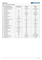
iMkockerlingStutzrad / Land wheel / Roue bequille Pos.
Open the catalog to page 13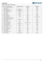
(JKOCKERLINGDrillboxhalter/ Drillbox frame/ Chassis Pos.
Open the catalog to page 17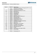
Grasmaster (BKdCKERUNG Bodenantrieb Spornrad / Tail wheel / Molette de I'eperon
Open the catalog to page 21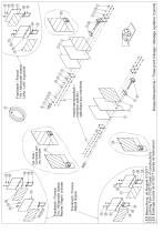
kpl. Satz / Complete set / Jeu complet LED Beleuchtung ab Baujahr 01/2017 LED Lichting from 01/2017(year of construction) LED Éclairage à partir de 01/2017 (année de fabrication) Frankreich / France Rebell classic Frankreich / France Trio / Allrounder classic Rechts / Right / à droite Dreipunktmaschine / Three point linkage / Attelage système 3 points Frankreich / France Trio / Allrounder classic Links / Left / à gauche maschinenspezifisch / machine specific / spècifique aux machines
Open the catalog to page 26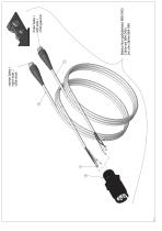
rechte Seite / right side / côté droit Beleuchtungskabelsatz 668 040 / Cable set 664 040 / Jeu de câbles 664 040 linke Seite / left side / côté gauc
Open the catalog to page 28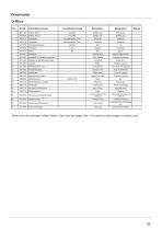
Siehe auch die nachsten beiden Seiten / See next two pages, too / Voir aussi les deux pages suivantes, svp.
Open the catalog to page 33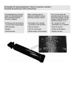
Fur die Bestellung von Dicht-satzen fur Hydraulikzylinder bitte unbedingt folgende Nummern angeben: • ID-Nummer des Hy.-Zylinder (auf dem Kolben eingeschlagen) When ordering seals for hydraulic cylinders indicate following numbers, please: • ID-number of hy. cylinder (is printed on the cylinder) Pour la commande des pochettes de joints pour les verins hydrauliques, veuillez indiquer imperativement les numeros suivants.s.v.p.: • ID - numero du verin (estampille sur le cylindre)
Open the catalog to page 44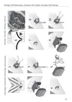
Demontage / Disassembly / Démontage / Демонстрация Montage /Assembly / Montage /Монтаж
Open the catalog to page 45
908806 Ersatzteilliste GRASMASTER KÖCKERLING behält sich technische Änderungen, die der Weiterentwicklung dienen, vor. Landmaschinenfabrik Köckerling GmbH & Co. KG France SAS Lindenstraße 11-13 Zone Industrielle des Vaux 33415 Verl F 61500 Essay Telefon +49 (0) 52 46 - 96 08-0 /-16 /-22 02 & 33Co. 27 69 Landmaschinenfabrik Köckerling Tél.: GmbH KG16 Telefax +49 (0) 52 46 - 96 08-55 Fax: 02 33 29 43 19 Lindenstraße 11-13 | 33415 Verl www.koeckerling.de [email protected] Tel. +49.5246.96080 | Fax. +49.5246.960821 [email protected] www.koeckerling.com
Open the catalog to page 48All Köckerling GmbH & Co. KG catalogs and technical brochures
 Speed Drill
56 Pages
 Vector 460 / 620
196 Pages
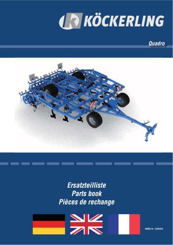 Quadro
148 Pages
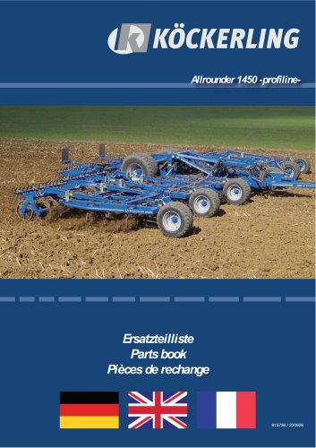 Allrounder 1450 -profiline-
128 Pages
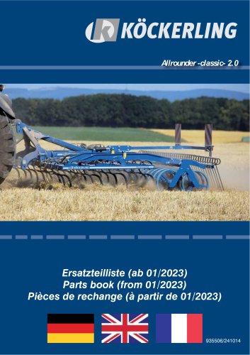 Allrounder-classic-2.0
152 Pages
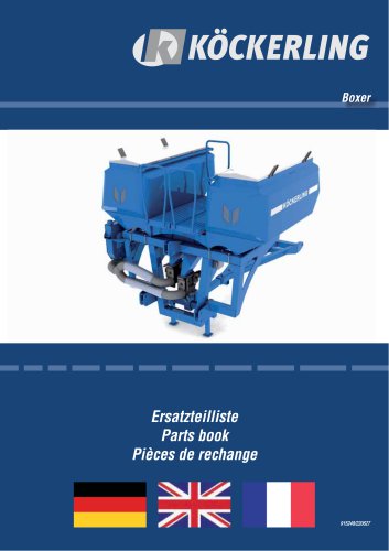 Boxer
Boxer96 Pages
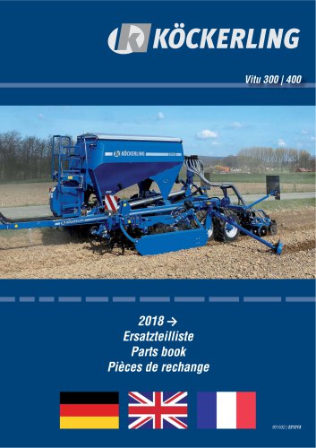 Vitu 300 - 400
184 Pages
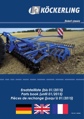 Rebell classic
44 Pages
 ALLROUND -classic-
80 Pages
- Seeder
- Vibro-cultivator
- Mounted vibro-cultivator
- Vertical tiller
- Seed drill
- Vibro-cultivator with roller
- 2-section disc tiller
- Harrow
- Towed vertical tiller
- Mechanical in line seeder
- Folding vibro-cultivator
- Mounted disc tiller
- Disc harrow with hydraulic adjustment
- Disc tiller with roller
- Tractor-mounted seed drill
- Disc seed drill
- Field cultivator with hydraulic adjustment
- Compacting land roller
- Towed seed drill
- Spring tine vibro-cultivator