- Catalogs
- Landoll Corporation
- Model 8530 Finisholl Operators Manual
Model 8530 Finisholl Operators Manual

Model 8530 Finisholl Operators Manual
The Landoll Model 8530 Finisholl manual provides essential safety information, including understanding safety statements and symbols such as Note, Notice, Caution, Warning, and Danger. It covers hydraulic safety, protective equipment, chemical safety, and emergency preparedness. Tire safety and the use of safety chains for towing are also emphasized.
This section details model specifications, including working and transport dimensions, tire sizes, and torque specifications for bolts and hydraulic fittings. Proper assembly and maintenance are ensured through these guidelines.
Instructions for assembling the 8530 Finisholl include frame and hitch assembly, tire installation, and hydraulic installation. Specific instructions are provided for various harrow installations, emphasizing correct alignment and hardware use.
Guidelines for preparing the tractor, attaching the implement, and operating hydraulic systems are included. The document covers leveling, depth stop adjustment, lubrication, and maintenance tips to ensure optimal performance and longevity.
This guide helps diagnose and resolve common issues, such as uneven field leveling and hydraulic problems, ensuring the equipment's functionality is maintained.
The Finisholl features hydraulic lift, fold, and disc gang systems. Proper connection and maintenance, including air purging and leak checks, are crucial for operation.
Transport guidelines include checking compliance with regulations, ensuring the implement is transported by a suitable tractor, and inspecting safety chains and tires.
Proper connection and function of LED lights are necessary for safe transport, adhering to local lighting regulations.
Horsepower requirements and operating speeds are specified, with emphasis on maintaining contact with the ground for lift wheels.
Adjustments for various harrow types are detailed, focusing on tine angles, reel height, and spring pressure to optimize performance based on field conditions.
Off-season storage practices include cleaning, inspecting, lubricating, and storing the unit in a protected environment to extend service life.
A revision log ensures users have access to the most current information regarding specifications and assembly instructions.
Catalog excerpts

Model 8530 Finisholl Operators Manual LANDOLL COMPANY, LLC 1900 North Street Marysville, Kansas 66508 (785) 562-5381 800-428-5655 ~ WWW.LANDOLL.COM F-756-0321
Open the catalog to page 1
Manuals for the 8530 Finisholl MANUAL NUMBER MANUAL NAME 8530 Finisholl Operator’s Manual 8530 Finisholl Parts Manual
Open the catalog to page 2
Introduction and Safety Information Understanding Safety Statements . . . . . . . . . . . . . . . . . . . . . . . . . . . . . . . . . . . . . . . . . . . . . Decal Safety . . . . . . . . . . . . . . . . . . . . . . . . . . . . . . . . . . . . . . . . . . . . . . . . . . . . . . . . . . . . . Transporting Safety . . . . . . . . . . . . . . . . . . . . . . . . . . . . . . . . . . . . . . . . . . . . . . . . . . . . . . . . Attaching, Detaching, and Storage . . . . . . . . . . . . . . . . . . . . . . . . . . . . . . . . . . . . . . . . . . . . Maintenance Safety . . . . . . . . . . . . . . . . ....
Open the catalog to page 3
Leveling (Front-to-Rear) . . . . . . . . . . . . . . . . . . . . . . . . . . . . . . . . . . . . . . . . . . . . . . . . . . . . 4-9 Depth Stop Adjustment . . . . . . . . . . . . . . . . . . . . . . . . . . . . . . . . . . . . . . . . . . . . . . . . . . . . . 4-9 Disc Blades . . . . . . . . . . . . . . . . . . . . . . . . . . . . . . . . . . . . . . . . . . . . . . . . . . . . . . . . . . . . . 4-10 Disc Gang Operation . . . . . . . . . . . . . . . . . . . . . . . . . . . . . . . . . . . . . . . . . . . . . . . . . . . . . . 4-10 Disc Gang Assembly . . . . . . . . . . . . . . . . . . . . . ....
Open the catalog to page 4
Introduction and Safety Information Introduction The Landoll Model 8530 Finisholl is a quality product designed to give years of trouble free performance. By following each section of this manual, your system will perform as designed for you and your operation. CHAPTER 1 Gives basic instructions on the use of this manual and understanding the safety statements. Gives product specifications for the equipment. These specifications supply lengths and measures for your equipment. A Standard Bolt Torque Table is provided to give guidelines for bolt torques to be used when servicing this product. Contains...
Open the catalog to page 5
INTRODUCTION AND SAFETY INFORMATION Understanding Safety Statements You will find various types of safety information on the following pages and on the machine signs (decals) attached to the vehicle. This section explains their meaning. The Safety Alert Symbol means ATTENTION! YOUR SAFETY IS INVOLVED! NOTE Means that failure to follow these instructions could cause damage to the equipment or cause it to operate improperly. NOTICE Special notice - read and thoroughly understand Caution means serious equipment or other property damage can occur if instructions on this label are not properly followed....
Open the catalog to page 6
INTRODUCTION AND SAFETY INFORMATION 6. Attach the safety chain to the tractor recommended drawbar support. Provide only enough slack in the chain for turning. Do not attach the safety chain to an intermediate support. Safety chain must have rating greater than the gross weight of the towed implement(s). Replace the safety chain if it is worn or damaged in any way. 7. Verify that all hydraulic hoses and electrical wiring between the tractor and implement are safely routed to avoid damage. 8. Check implement tire pressure for correct inflation. Verify that lug nuts are properly torqued before transporting....
Open the catalog to page 7
INTRODUCTION AND SAFETY INFORMATION Tire Safety Safety Chain 1. Tire changing can be dangerous and should be performed by trained personnel using correct tools and equipment. 2. When inflating tires, use a clip-on chuck and extension hose long enough to allow you to stand to one side, not in front of or over the tire assembly. Use a safety cage if available. 3. When removing and installing wheels use wheel-handling equipment adequate for the weight involved. 1. Use a chain with a strength rating equal to or greater than the gross weight of towed machinery, which is 10,100 pounds minimum in accordance...
Open the catalog to page 8
Standard Specifications Model Specifications 8530 Finisholl Model Number Working Width Transport Width Transport Height Number of Shanks Shanks per Section Tire Size Spindle Size Wheel Bolt Pattern 3” Center 3” Center Frame, Frame, 2-1/4” Wings 2-1/4” Wings 8 Bolt Wheels NOTE: Specifications Are Subject To Change Without Prior Notification Tire Inflation Tire Size Tire Manufacturer Ply/Load Rating Specific Bolt Torques Lug Bolts & Nuts 9/16-18 Lug Bolts & Nuts (Heavy Duty Disc) 5/8-18 Lug Bolts & Nuts (Heavy Duty Disc) Disc Gang Shafts
Open the catalog to page 9
STANDARD SPECIFICATIONS General Torque Specifications (rev. 4/97) TORQUE SPECIFIED IN FOOT POUNDS - This chart provides tightening torques for general purpose applications when special torques are not specified on process or drawing. Assembly torques apply to plated nuts and capscrews assembled without supplemental lubrication (as received condition). They do not apply if special graphite moly-disulfide or other extreme pressure lubricants are used. When fasteners are dry (solvent cleaned) add 33% to as received condition torque. Bolt head identification marks indicate grade and may vary from...
Open the catalog to page 10
STANDARD SPECIFICATIONS Hydraulic Fitting Torque Specifications TORQUE IS SPECIFIED IN FOOT POUNDS- 37o JIC, ORS, & ORB (REV. 10/97) This chart provides tightening torques for general purpose applications when special torques are not specified on process or drawing. Assembly torques apply to plated nuts and capscrews assembled without supplemental lubrication (as received condition). They do not apply if special graphite moly-disulfide or other extreme pressure lubricants are used. When fasteners are dry (solvent cleaned) add 33% to as received condition torque. Bolt head identification marks...
Open the catalog to page 11
STANDARD SPECIFICATIONS Figure 2-1: Shank and Light Bracket Placement - 19’ (Left Half)
Open the catalog to page 12
STANDARD SPECIFICATIONS Figure 2-2: Shank and Light Bracket Placement - 19’ (Right Half)
Open the catalog to page 13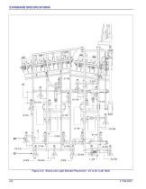
STANDARD SPECIFICATIONS Figure 2-3: Shank and Light Bracket Placement - 22’ & 25’ (Left Half)
Open the catalog to page 14All Landoll Corporation catalogs and technical brochures
 Landscape Seeders
2 Pages
 Agricultural Seeders
6 Pages
 Till 'N Seed®
6 Pages
 Food Plot Seeder
4 Pages
 Pulvi-Mulcher
16 Pages
 Pulverizer
4 Pages
 Chisel Plow
4 Pages
 Soil Builder
4 Pages
 Sub Soiler
2 Pages
 Zone Commander
8 Pages
- Jympa seeder
- Jympa field cultivator
- Jympa mounted field cultivator
- Jympa seed drill
- Vertical tiller
- Jympa field cultivator with roller
- 2-section disc tiller
- Soil loosener
- Rigid tine vibro-cultivator
- Mechanical in line seeder
- Towed vertical tiller
- Jympa folding field cultivator
- Mounted disc tiller
- Jympa tractor-mounted seed drill
- Disc tiller with roller
- Disc harrow with hydraulic adjustment
- Grading blade
- Field cultivator with hydraulic adjustment
- Jympa fixed field cultivator
- Towed seed drill