- Catalogs
- Logosol AB
- B1001 HYDRAULIC
B1001 HYDRAULIC
1 /64Pages

B1001 HYDRAULIC
1 /64Pages
Catalog excerpts
USER MANUAL Part no. 0458-395-0691 ROTATE SUPPORT
Open the catalog to page 1
THANKS FOR CHOOSING A LOGOSOL MACHINE! We are very pleased that you have demonstrated your confidence in us by purchasing this machine and we will do our utmost to meet your expectations. LOGOSOL has been manufacturing sawmills since 1989, and in that time we have supplied approximately 50,000 machines to satisfied customers the world over. We are concerned with your safety and ensuring that you achieve the best possible results with your machine. We therefore recommend that you take the time to carefully read this user manual before using the machine. Remember that the machine itself is only...
Open the catalog to page 2
TABLE OF CONTENTS Description of machine Safety instructions Technical data Component parts: Connecting valve/hydraulic cylinders Hydraulic hose First start-up Exploded views Hydraulic diagram
Open the catalog to page 3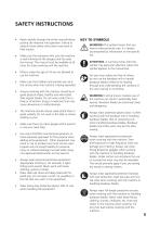
SAFETY INSTRUCTIONS • Read carefully through the entire manual before putting the machine into operation. Failure to observe these safety instructions may result in fatal injuries. Make sure that everyone who uses the machine is well informed of the dangers and has read the manual. The manual must be available at all times for those working with the machine. Minors under the age of 18 are not allowed to use the machine. Make sure that children and animals are not in the vicinity when the machine is being operated. Anyone working with the machine should be in good physical shape, healthy and well-rested....
Open the catalog to page 5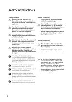
SAFETY INSTRUCTIONS Safety distance Before each shift: Warning! Fire risk. Hydraulic oil is flammable, do not perform hot work in the vicinity of hydraulic components and equipment. Check hydraulic hoses, couplings and cables for visible damage. Warning! Do not exceed the maximum weights specified for the equipment. Overload can entail sudden breakdowns making the work area dangerous Warning! Do not exceed the maximum weights specified for the equipment. Overload can entail sudden breakdowns making the work area dangerous Always check that the specified amount of hydraulic oil is in the tank...
Open the catalog to page 6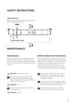
SAFETY INSTRUCTIONS Safety distance: Make sure that nobody is within the safety distance when working with the machine. OPERATIONAL AREA MAINTENANCE MAINTENANCE BEFORE WORKING ON THE MACHINE Periodic maintenance of the machine expected to be performed by the operator is described in this section. Be sure to follow the specified maintenance intervals, as this is the basis for good function of the machine. Always unplug the power cable at the mains before starting service or adjustment. Check that the power cable, plugs and switches are in good condition and undamaged. Clean all parts of the machine...
Open the catalog to page 7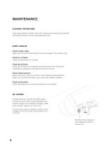
MAINTENANCE CLEANING THE MACHINE Clean the bandsaw mill after each shift. Sweep away shavings and sawdust around the functions and on and around the rails. EVERY START-UP Check scraper rings: Make sure that dirt and shavings do not accumulate on the scraper rings. Check for oil leaks: Check all connections for oil leaks Check the oil level: Check the oil level in the hydraulic tank before each shift. Follow the maintenance schedule in the engine instruction manual. Check safety features: Before each shift, check the function of the following safety features: Make sure that the valve levers return...
Open the catalog to page 8
TECHNICAL DATA LOGOSOL HYDRAULIC B1001/B751 01-00556 TOEBOARD Stroke length toeboard Diameter roller 01-00627 LOG CLAMP Vertical stroke Minimum clamp width Maximum clamp width 01-00584 LOG SUPPORT Vertical stroke POWERPACK Output 4L / 5L There is approximately 10L of oil in the system with all functions connected
Open the catalog to page 9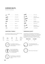
SCREWS/NUTS Definition of the fasteners. Centre bolt Allen screw Cross screw Allen screw (partially threaded) Slotted screw Locking screw Hex bolt (partially threaded) Flange screw Flange screw (partially threaded) Flat washer Carriage bolt ADDITIONAL SYMBOLS The following symbols are used in addition to those shown above to describe part design. The dimensions of the fasteners are printed as a diameter dimension (M) ISO 68-1. This is followed by a length dimensions for bolts/screws; the dimension of a bolt/screw is the part of the bolt/screw that disappears into the material in which it is mounted....
Open the catalog to page 10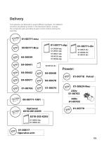
Delivery The hydraulics are delivered in several different packages. The different functions are packed as shown in the illustration below. Arrange the component parts according to each function before starting the assembly.
Open the catalog to page 11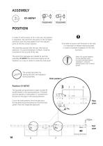
POSITION In order for all functions to fit on the rails, the position is important. We start from the joints on the rail pipes and then count the hole pattern from the relevant joints to find the correct position. To be able to mount new functions in the rails, it is important to release existing log beds in order to facilitate installation of the new functions. The assembly assumes that the saw rails have an extension. If a second extension is fitted, it shall be mounted on the far end of the rails. The parts from packages are needed to start the assembly. 01-00767 We recommend laying out all...
Open the catalog to page 18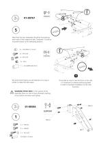
5 Note that the two toeboards should be mounted on each side of their respective bed. Toeboard (1) shall be mounted closest to the operating position. We recommend laying out all fasteners on a tray or similar to make the task easier. To be able to mount new functions in the rails, it is important to release existing log beds in order to facilitate installation of the new functions. WARNING PINCH RISK! In this section of the assembly there is a risk of injury through crushing, so be careful and wear work gloves.
Open the catalog to page 20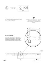
We recommend laying out all fasteners on a tray or similar to make the task easier. To be able to mount new functions in the rails, it is important to release existing log beds in order to facilitate installation of the new functions. Position 01-00627 The log beds are positioned on pipe number 4 viewed in the sawing direction. The log clamp is then placed on hole patterns 3 and 4 counted from the joint on the pipe in the sawing direction.
Open the catalog to page 24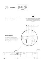
We recommend laying out all fasteners on a tray or similar to make the task easier. To be able to mount new functions in the rails, it is important to release existing log beds in order to facilitate installation of the new functions. Position 00-00102 The log beds are positioned on pipe number 4 viewed in the sawing direction. The beds are then placed on hole pattern 6 counted from the joint on the pipe in the sawing direction. Sawing direction
Open the catalog to page 28All Logosol AB catalogs and technical brochures
 Big Mill System
52 Pages
 B751 PRO BAND SAWMILL
92 Pages
 F2+ CHAIN SAWMILL
52 Pages
 Product Catalog 2022
68 Pages
 F2 Chain sawmill
16 Pages
 Multi-Head Planer/Moulders
40 Pages
 product_catalogue
96 Pages
 big_mill_system_manual
52 Pages
 moulding_catalogue
92 Pages
 b1001
b100192 Pages
