- Catalogs
- Logosol AB
- F2+ CHAIN SAWMILL
F2+ CHAIN SAWMILL
1 /52Pages

F2+ CHAIN SAWMILL
1 /52Pages
Catalog excerpts

LOGOSOL F2+ CHAIN SAWMILL EN
Open the catalog to page 1
THANK YOU FOR CHOOSING A LOGOSOL MACHINE! We are very pleased that you have demonstrated your confidence in us by purchasing this sawmill, and we will do our utmost to meet your expectations. Logosol has been manufacturing sawmills since 1989. In that time we have supplied approximately 50,000 machines to satisfied customers the world over. We care about your safety as well as we want you to achieve the best possible results with your sawmill. We therefore recommend that you take the time to carefully read this user manual from cover to cover in peace and quiet before you begin using the saw....
Open the catalog to page 2
TABLE OF CONTENTS Safety instructions Technical data Adjustment: guide rail Components: boxes in shipment Components: guide rail Sawing: step by step Sawing: tips and advice Components: bags of smaller componets 12 Components: bolt bags Cutting equipment Tools required Material drying Assembly: guide rail Assembly: chainsaw
Open the catalog to page 3
SAFETY INSTRUCTIONS • Read carefully through the entire user manual before starting to operate the Logosol F2+. Failure to observe these safety instructions may result in fatal injuries. Always wear protective clothing and use personal protective equipment: Never operate the sawmill wearing loose-fitting clothes, overall coats or similar. Make sure that everyone who uses the sawmill is well informed of the dangers and has read the user manual. The user manual shall always be available to the persons working with the sawmill. This also applies where the sawmill is sold or loaned out. Use safety...
Open the catalog to page 4
Safety distances Respect the safety distances. The safety distance is 8 m for the operator and 15 m for persons other than the operator. The illustration below shows the sawmill from above. The operator is to remain within the area marked with a dashed line (- - - -) when the saw is in operation. The operator is not to stretch over the guide rail when the sawmill is in operation. Check that the cutting equipment is correctly assembled. Risk of chain breaks! Check that saw unit is pushed fully into position on the guide rail. Throw-out risk on start up! The sawmill is not to be in any other position...
Open the catalog to page 5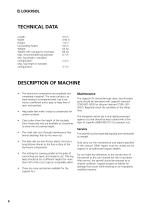
TECHNICAL DATA Length: 4.0 m Width: 0.92 m Height: 1.0 m Log loading height: 0.6 m Weight: 65 kg Weight with carriage for chainsaw: 68 kg Max. recommended log diameter: 0.7 m Min. log length in standard configuration: 2.4 m Max. log length in standard configuration: 3.7 m The aluminium components are anodized and completely rustproof. The outer surface is as wear-resistant as tempered steel, has a low friction coefficient and is easy to keep free of resin and sawdust. Adjustable feet make it easy to compensate for uneven surfaces. The crank axle runs through maintenance-free bronze bearings that...
Open the catalog to page 6
COMPONENTS: BOXES IN SHIPMENT Your LOGOSOL F2 shipment consists of the following boxes. Check that all of these boxes are included in the shipment when receiving it. 5 metres (three log lifters) 4530-000-2005 1 x 4525-001-0010 6 metres (three log lifters) 4530-000-2006 1 x 4525-001-0010
Open the catalog to page 7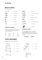
BOLTS & NUTS Definition of fasteners. Shoulder bolt Allen bolt Phillips bolt Partial thread Allen bolt Slotted bolt Partial thread hex bolt Flange bolt Partial thread flange bolt Carriage bolt Flat washer Spare parts ADDITIONAL SYMBOLS The following symbols are used as supplements to the symbols above to describe the design or function of the fasteners. DIAMETER & LENGTH The size of a fastener is written as a diameter measurement (M) ISO 68-1. For bolts, this is followed by a length measurement. The length of the bolt is measured from below the head to the tip of the bolt. TOOLS REQUIRED Verktyg...
Open the catalog to page 14
Scan this QR code for complete instruction video. For best viewing options, see the video on the YouTube app or webpage. Scan QR code in each step for individual video. Here we go! We recommend that you start with assembling the log lifters. These are identical, and all components needed are found in the log lifter boxes. We recommend that you place all fastening elements on a tray or the like to facilitate finding the bolts, nuts, etc. Open one of the log lifter boxes and start assembling. Wear protective gloves during assembly, as there may be sharp edges. Symbol: Assembly
Open the catalog to page 15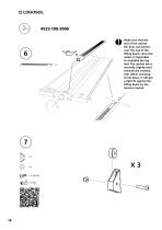
Make sure that the end of the ratchet bar does not extend over the end of the lifting beam, since this makes it impossible to assemble the log bed. The ratchet bar is normally slightly bent towards the toothed side. When screwing it into place, it will get a tight fit against the lifting beam by the tension created.
Open the catalog to page 18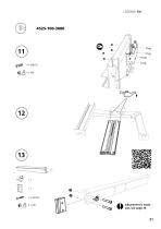
Adjustment is made last, see page 39.
Open the catalog to page 21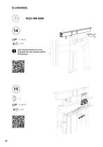
Note that the bolts have to be threaded into the log bed and the lifting beam.
Open the catalog to page 22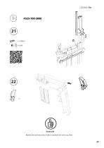
Good job! Repeat the assembly steps 1-22 to assemble the other log lifter.
Open the catalog to page 27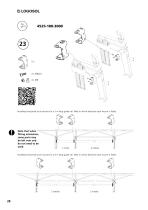
Installing horizontal strut mounts for a 5 m long guide rail. Note in which direction each mount is fitted. Note that when fitting extensions, some parts may be left over and do not need to be used. Installing horizontal strut mounts for a 6 m long guide rail. Note in which direction each mount is fitted.
Open the catalog to page 28
Good job! To continue with the next step you need the parts from the guide rail boxes. Open the guide rail boxes. Symbol: Assembly
Open the catalog to page 31
The guide rail sections can differ slightly in size. To ensure that the saw carriage will slide smoothly over the joints, the guide rail sections may need to be sanded down a little in the corners. Use the supplied sandpaper to rub off the four corners of the guide rail section, as shown in the illustration. The joint coupler should be fitted in the guide rail with its opening facing up, as in the illustration. The lock nut should be positioned correctly in the nut recess. The bolt should not be tightened when the joint coupler is installed in the guide rail ends. Note that each guide rail section...
Open the catalog to page 32
Now it is time to assemble the saw carriage. Symbol: Assembly
Open the catalog to page 35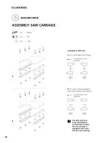
Assembly of slide rails A. For a removable saw carriage. The direction of the guide bar B. For a saw carriage equipped with crank and bar nose steering. The direction of the guide bar The slide rails have to be assembled as in illustration B when the saw carriage is equipped with crank and bar nose steering.
Open the catalog to page 36All Logosol AB catalogs and technical brochures
 B1001 HYDRAULIC
64 Pages
 Big Mill System
52 Pages
 B751 PRO BAND SAWMILL
92 Pages
 Product Catalog 2022
68 Pages
 F2 Chain sawmill
16 Pages
 Multi-Head Planer/Moulders
40 Pages
 product_catalogue
96 Pages
 big_mill_system_manual
52 Pages
 moulding_catalogue
92 Pages
 b1001
b100192 Pages
