
- Catalogs
- Micro-Trak Systems, Inc.
- MT-2405F™ II 5-BOOM AUTOMATIC RATE CONTROL REFERENCE MANUAL

MT-2405F™ II 5-BOOM AUTOMATIC RATE CONTROL REFERENCE MANUAL

MT-2405F™ II 5-BOOM AUTOMATIC RATE CONTROL REFERENCE MANUAL
The MT-2405F™ II is an electronic control system designed to optimize the application rates of liquid chemicals and fertilizers, enhancing yield and cost-effectiveness. It supports both English and Metric measurements and requires careful installation and operation as per the manual.
Micro-Trak offers a warranty for defects in materials or workmanship for one year, extendable to three years for certain components upon registration. Exclusions apply for expendable parts and damages due to misuse or unauthorized modifications.
The manual provides detailed instructions on system layout, including inline and bypass plumbing, component assembly, and electrical installation. Key components include the display console, speed sensor, flowmeter, and various valves. Proper installation is crucial for optimal performance.
Calibration involves setting up the system for English or Metric units, entering calibration values, and configuring speed sensors. The manual outlines procedures for pre-field system checks and operational guidelines, including console functions and switch operations.
A comprehensive troubleshooting section addresses common issues, providing messages, warnings, and a plumbing troubleshooting chart to assist users in diagnosing and resolving problems.
The MT-2405F™ II aims to provide efficient and profitable operation for agricultural applications, with a focus on quality and performance at a low cost. Users are encouraged to register their product for extended warranty benefits.
The document provides a comprehensive guide on the MT-2405F II system, including appendices covering various installation kits, calibration procedures, and system layouts. Key sections include the Boom Shut-off Relay Kit, Speed Sensor Mounting, and Flowmeter Calibration.
The MT-2405F II system is detailed with in-line and bypass plumbing layouts. Key components include the switch box, boom valves, speed sensor, and flowmeter. Notably, some items like the boom valves and wiring are not included with the system.
Before installation, verify the presence of essential components such as the console mount kit, extension cables, and speed sensor kit. The document lists part numbers for easy identification.
Mounting the Display Console: Choose a location that is visible and accessible, avoiding direct sunlight and high temperatures. Use the provided hardware to secure the console.
Electrical Installation: Connect the MT-2405F II to a 12-volt DC negative ground system. Ensure proper grounding and use a 4-amp in-line fuse for unprotected circuits. The system's non-volatile memory retains data without constant power.
This section explains connecting the MT-2405F II to existing boom control switches. It supports up to five boom switches, with detailed instructions on using moisture-resistant tap connectors.
For radar or GPS speed sensors, refer to Appendix I. Magnetic speed sensors can be installed on non-driven wheels or drive shafts, with guidelines on magnet spacing and polarity.
Detailed appendices provide additional instructions for specific components and configurations, such as the NH3 system layout, radar adapter cables, and conversion charts.
The document provides detailed instructions for the installation and setup of the MT-2405F II system, focusing on the proper placement and connection of magnets and sensors. Magnets must be evenly spaced around the wheel or drive shaft, with a minimum distance of 1 inch apart. The speed sensor is mounted directly over the magnet, ensuring a constant spacing between the magnets and the sensor tip.
Components required include the speed sensor cable, magnets, mounting bracket, and cable ties. The number of magnets varies based on wheel circumference, with specific configurations provided for both English and metric measurements. The speed sensor cable, identified by its green body, connects to a 3-pin connector marked with a yellow cable tie.
The MT-2405F II system can interface with various speed sensing equipment, including GPS and radar sensors. Options include the Astro GPS Speed Sensor and Vansco Radar Speed Sensor, each offering specific advantages in terms of installation and performance.
The flowmeter must be installed in the main boom line, away from intense vibration and at least 12 inches from the servo valve. The flow sensor cable, with a green body, connects to the main harness cable marked with a green tie.
Instructions are provided for installing pressure relief valves and range adjust valves to manage pump output and system pressure. The servo valve should be installed in an unrestricted return line, with specific calibration required for bypass or inline operations.
The MT-2405F II console features a liquid crystal display for monitoring various parameters such as volume, rate, and area. Calibration modes allow for setting flow rates and target application rates.
Recommendations include storing the console in a cool, dry location when not in use and ensuring the flowmeter is not exposed to excessive pressure or temperature. Specific chemicals may damage the turbine, and users are advised to consult chemical manufacturers if in doubt.
The document provides detailed instructions for operating and calibrating the MT-2405F II console, which is used for managing agricultural spraying equipment. It includes sections on specifications, calibration procedures, and operational guidelines.
The MT-2405F II console can display information in either American English or Metric units. It is factory-programmed for English but can be switched to Metric mode. The console includes features such as distance measurement, area/hour display, speed calibration, and flow calibration.
- Entering Calibration Mode: To enter calibration mode, the vehicle must be stopped, and all booms turned off. The 'cal' button is held until the 'cal' icon appears. Calibration can be done while moving, but it is not recommended.
- Calibration Values: Users can adjust various calibration values such as target rate, adjust rate, flow calibration, minimum flow, width calibration, and speed calibration. Each value is adjusted using the '+' and '-' buttons.
- Speed Calibration: The speed calibration involves determining the circumference of the sensor-equipped wheel and dividing by the number of magnets installed. Fine-tuning is recommended for optimal accuracy.
- Flow Calibration: This is used to calibrate the flow meter for accurate liquid measurement. The flow calibration value is specific to the solution being used.
- Mode Selection: The console can operate in automatic or manual mode, with the ability to switch between the two using the Auto/Man key.
- Resetting Counters: To reset counters such as distance, total flow, or area, the system must be in hold or all booms turned off, and the 'reset' key pressed for three seconds.
- Warning Indicators: A warning light indicates over or under-application of 10% of the target rate and is also lit during calibration.
This mode is used to set system parameters that rarely need adjustment. It is accessed by holding the Auto/Man and Cal buttons while turning the console on. Parameters include units, valve voltage, material, valve response speed, and auto shutoff settings.
- Switching between English and Metric modes may alter previously entered calibration values.
- Calibration must be exited to save any changes made.
- Test speed allows for pre-field checks by simulating ground speed without actual movement.
The system allows selection between 8 and 12 volts for the servo valve, with a factory setting of 12 volts. For older Micro-Trak servo valves, 8 volts is recommended. Material selection is between liquid (H2O) and anhydrous ammonia (NH3), with specific instructions for NH3 provided in an appendix.
Valve response speed can be adjusted from -2 to 3 to optimize system performance with different valve speeds. Caution is advised when increasing speed for fast valves to avoid instability. Special calibration settings can be saved by exiting the calibration mode.
The system allows setting the tank size and alarm set points. The tank size can be set from 1 to 65,535 units, and the alarm set point triggers a warning when the tank level is low.
Auto shutoff can be enabled to minimize flow when the system is on hold. A delay can be set from 0 to 4 seconds to accommodate slow ball valves.
Before spraying, a pre-field system checkout is recommended to ensure proper valve settings and nozzle selection. This involves setting maximum and minimum application speeds and adjusting valves to achieve desired application rates. The system should be checked with clean water before using chemicals.
The MT-2405F II system can operate in manual or automatic mode. In manual mode, the application rate is adjusted with buttons, while in automatic mode, the system maintains the calibrated rate despite speed changes. The system can be turned on/off via the ignition switch or an optional switch kit.
The console displays various operational data based on the rotary switch position. The run/hold switch controls boom activation, and the auto/manual button toggles control modes. In automatic mode, the system requires a speed signal to operate booms.
The document provides detailed instructions and specifications for operating the MT-2405F II console, focusing on its various modes, controls, and troubleshooting procedures.
The console operates in automatic ('auTo') and manual ('Man') modes. In 'auTo' mode, the target application rate can be adjusted using the '+' and '-' buttons, which modify the rate by a calibrated adjust rate (Delta). In 'Man' mode, these buttons control the servo valve to adjust the application rate.
The system monitors boom switches to calculate the application area based on active boom widths. The console displays which booms are active when the rotary switch is set to 'raTE' or 'arEa/Hour'.
The rotary switch allows users to view different functions such as area covered, distance traveled, application rate, and tank volume. Each function is associated with specific display settings and operational modes.
A red warning light alerts users when the application rate deviates by more than 10% from the target rate or when the tank level is low. It also indicates when the console is in calibration mode.
This feature allows real-time adjustments to the application rate using the '+' and '-' buttons, provided the console is in 'auTo' mode and the rotary switch is set to 'raTE'.
The document outlines procedures for resetting area, distance, and volume counters. It emphasizes using the '+' button to select counter sets and warns against using the '-' button, which clears counters.
The document includes a troubleshooting section addressing common issues such as power problems, inaccurate readings, and sensor malfunctions. It provides specific steps for diagnosing and resolving these issues.
Users are advised not to open the console due to warranty protection. Many operational issues are attributed to installation or operational errors rather than equipment failure.
Ensure all MT-2405F II cables are kept away from the radio, its antenna, and power cables to prevent interference. Avoid placing cables near ignition wires or install an ignition suppressor. Reroute cables away from electric solenoids and air conditioning clutches.
Check the Valve Speed calibration number if the rate overshoots or oscillates. Adjust the Valve Speed setting if necessary. Ensure the console is in the correct measurement mode (English or metric). Reset counters if they read 'OFL' due to exceeding maximum count.
For sluggish automatic mode operation, verify the Valve Speed setting. Test the console by connecting it to a known working harness or E-PoP display stand. Use an ohmmeter or continuity tester to check the harness.
Route wires away from ignition wires and inductive loads to prevent erratic operation. Check the power source with MT-101 or a test light. Ensure accessory power wires are not open or shorted.
Test Hall-effect sensors by grounding pin C and connecting 12 volts to pin B. Use an ohmmeter to check resistance changes when exposed to magnetic poles. For radar speed sensors, follow a series of steps to check voltage and response.
Test speed, flow, and remote run/hold inputs by checking voltage and using jumper wires to simulate sensor signals. Ensure the flowmeter turbine spins freely and registers flow.
Test the servo valve with a known working console or a 9-volt battery. Ensure proper plumbing to avoid pressure drops and ensure optimal performance. Follow guidelines for pump inlet, agitation, servo, and flowmeter lines.
Address issues like pressure loss, insufficient pressure adjustment, and pressure fluctuations by checking for air-locks, restrictions, and proper valve settings. Ensure hoses are appropriately sized and supported to prevent sagging and kinking.
Adjust tank shut-off, agitation shut-off, and pressure relief valves for optimal operation. Ensure valves are fully open during operation and adjust pressure relief valves to avoid excessive pressure.
- Range Adjust Valve: Used when the pump is oversized. It allows liquid to bypass the pump to prevent system overload. Start with the valve closed and adjust based on throttle valve settings.
- Throttle Valve: Controls high-end limits to enhance servo performance. Begin with it fully open and adjust to maintain desired pressure levels. A needle valve is recommended over a ball valve for ease of adjustment.
- Relief Solenoid Valve: Optional component to prevent excessive pressure when boom valves are off.
- Assembly Instructions: Ensure proper placement of the turbine and o-ring. Tighten screws evenly and check for a rattling sound to confirm correct assembly.
- Cleaning and Maintenance: Disassemble carefully for cleaning. Use warm water and mild detergent, avoiding solvents. Inspect for wear and replace parts as necessary.
- Remote Run/Hold Sensor: Controls solenoid valves based on console status. Requires a relay kit for proper operation.
- Wiring Instructions: Detailed steps for connecting relay wires to the solenoid control switch box.
- Speed Sensor Installation: Instructions for mounting speed sensors on various vehicle types, ensuring proper spacing and alignment.
- Calibration Procedures: Steps for fine-tuning speed and distance calibration values, with and without a run/hold switch.
1. Measure a distance of 1000 feet (500 meters) and mark the start and end points.
2. With the console on, set the run/Hold switch to Hold and ensure the display shows 0. Reset if necessary.
3. Drive the course, using a vehicle marker to start and stop the distance counting function.
4. Activate the distance counting by switching to Run at the start marker and to Hold at the end marker.
5. Enter calibration mode by holding the 'cal' key, adjust the displayed distance using '+' or '-' keys to match the actual distance driven.
6. Verify calibration by repeating the procedure and record the calibration number for future reference.
1. Fill the sprayer tank with at least 100 gallons of water.
2. Purge air from lines by running the pump and turning on booms.
3. Reset the volume counter on the console.
4. Run a known amount of water through the system.
5. Compare the console's volume reading with the actual amount of water used.
6. If necessary, enter calibration mode and adjust the flowmeter calibration value to match the actual volume.
7. Record the new calibration value for future reference.
Console and Switch Box Mounting
- The console can be mounted using a suction cup or a magnetic plate.
- Ensure the console is connected to a 12-volt DC electrical system.
Speed Sensor Installation
- Connect the speed sensor cable to the main harness using the correct connectors.
- Ensure proper connection to avoid errors in speed and flow measurements.
- Install the NH3500 plumbing panel on the applicator, ensuring proper hose lengths to prevent kinking.
- Use NH3 compatible thread sealing compounds for all pipe fittings.
- Ensure the manifold hose is properly connected to the servo valve outlet.
Before installing the liquifier plumbing panel, remove it from the shipping board and reposition the mounting bracket for easy access to the strainer clean-out plug. Ensure all brackets rest flat on the mounting surface and tighten carriage bolts once aligned.
Remove existing metering valves and install a new manifold if necessary. Ensure no positive shut-off valves are between the liquifier kit shut-off valve and the knives. Attach the plumbing panel to the tool bar frame and connect hoses appropriately, checking for proper lengths to avoid kinking.
Connect the supplied vapor hoses to the steel vapor tubes, ensuring enough length to prevent kinking. Secure hoses with clamps and cable ties. Weld steel vapor tubes to the back of liquid tubes, ensuring electronic equipment is disconnected before welding.
Use the main wiring harness designed for anhydrous ammonia applicators, connecting it to the main plumbing panel harness with optional extension cables if needed.
The console calculates rates and totals in lbs. (kg) of nitrogen or anhydrous ammonia. Enter standard calibration mode by turning off the shutoff valve and pressing the cal button. Adjust calibration factors for accurate measurements.
Enter the flow cal value from the flowmeter's metal tag and fine-tune as necessary. Set the target rate and adjust rate for on-the-go changes. Enter a minimum flow rate to prevent applying below recommended rates.
Measure the working width accurately for precise application rates. Exit calibration by pressing and holding the CAL button.
Perform this procedure on a straight, level tract of ground similar to actual field conditions. Measure a 1000 feet (500 meters) distance and adjust the calibration value based on the actual distance driven.
Start with a full nurse tank and apply at least 1,000 pounds of NH3. Compare the console's volume reading with the known amount applied and adjust the flowmeter calibration value if necessary.
1. Begin with a full nurse tank and ensure accurate weight measurement. Apply at least 1,000 pounds of NH3 for calibration accuracy.
2. With the valve switch off, select the desired volume/area counter using the “+” button and reset the display to 0.0.
3. Apply NH3 in the field until at least 1,000 pounds have been used, then weigh the partially used tank to determine the calibration weight.
4. Compare the console’s volume reading with the known NH3 amount. If the difference exceeds 2-3%, proceed with calibration.
5. Enter calibration mode by holding the cal button until the red warning light activates. Adjust the total flow value to match the NH3 run using the “+” or “-” buttons.
6. Record the new flowmeter calibration value for future reference.
7. Exit calibration by holding the cal button until the warning light turns off.
- Ensure equipment is in good condition and follow safety precautions.
- Operate the system in manual mode until the application rate stabilizes before switching to auto mode.
- Maintain adequate manifold pressure (15-60 PSI) to prevent vapor bubbles and ensure accurate readings.
- Regularly clean the strainer and check vapor tubes for obstructions.
- In hilly conditions, ensure the nurse tank dip tube remains submerged to avoid erratic operation.
- Frost build-up location can indicate system performance issues; clean the strainer to prevent excessive pressure drop.
- Opening the flowmeter voids the calibration value but may be necessary for cleaning or obstruction removal.
- Disassemble the flowmeter by removing bolts and cleaning the turbine and housing.
- Reassemble carefully, ensuring the turbine spins freely and the unit is properly sealed.
- Follow the manual procedure to verify flowmeter accuracy after reassembly.
- Always wear protective gear when handling NH3 equipment.
- Use anti-seize thread compound and thoroughly bleed hoses before disconnection.
- Completely evacuate NH3 apparatus before servicing.
- Various ball valve configurations and radar adapter cables are detailed for wiring assistance.
- A conversion chart provides English to Metric and Metric to English conversions for measurements.
- Replacement parts are available from Micro-Trak Systems, with part numbers and descriptions provided.
- Flowmeters:
- 13269 FM500 Flowmeter
- 11501 FM750 GFn Flowmeter
- 10131 FM750 SS Flowmeter
- 10899 FM750n Flowmeter - nH3 only
- 14348 FM1500n Flowmeter - nH3/liquifier
- Harnesses:
- 13758 Power, servo, boom universal harness
- 13757 Run/hold, speed, flow harness
- Kits:
- 13824 Terminal Block Kit
- 01559 Relay Kit (for auto Boom Shutoff)
- 14360 MT-2405F II Power (on/off) Switch Kit
- Servos:
- 14958 nH3500 Servo
- 14959 Liquifier Servo
- 21353 nH3 Servo Gear-head assembly
- Extension Cables: Optional 2-Pin, 3-Pin, and 10-Pin Metri-Pack 150 extension cables available in lengths of 5, 10, 15, 20, and 25 feet.
- The console mount kit is only available as a complete kit; individual components are not sold separately.
- Parts and design specifications are subject to change without notice.
- Manufactured in the U.S.A. by Micro-Trak Systems, Inc.
- Address: 111 E. LeRay Avenue / P.O. Box 99 / Eagle Lake, MN 56024-0099
- Contact: Toll-Free: (800) 328-9613, Phone: (507) 257-3600, Fax: (507) 257-3001
- Website: www.micro-trak.com
- Email: [email protected]
- © 2005-2012 Micro-Trak Systems, Inc.
- Printed in U.S.A.
- Part Number: 14904 Rev D
Catalog excerpts

5-Boom Automatic Rate Control
Open the catalog to page 1
automatic rate controller reference MANUAL The MT-2405F TM II is an electronic control system that can help you achieve maximum yields and operate more cost-effectively by providing the information you need to maintain proper application rates of liquid chemicals and fertilizer. The MT-2405FTM II has been designed for easy installation and op r ion. How v r, since each intalaion will vary depending on your e at e e s l t equipment, please take time to fa ilarze yourself with this manual and the actual components before beginning. Following m i i the procedures described in this manual...
Open the catalog to page 2
Micro-Trak® Warranty Micro-Trak (herein “Seller”) warrants to the original purchaser (herein “Buyer”) that, if any product or part of the product (herein “part”) proves to be defective in material or workmanship, upon inspection and examination by Seller, within one (1) year from the original date-of-purchase, and is returned to Seller with dated proof-of-purchase, transportation prepaid, within thirty (30) days after such defect is discovered, Seller will, at their option and sole discretion, either repair or replace said part, except that the warranty for expendable parts, including but not...
Open the catalog to page 3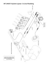
MT-2405F II System Layout - In-Line Plumbing SWITCH BOX SPEED SENSOR TANK SHUT-OFF VALVE* SERVO VALVE* RELIEF VALVE CONNECTION *ITEMS NOT INCLUDED WITH SYSTEM SWITCH BOX, BOOM VALVE WIRING, AND BOOM VALVES NOT PROVIDED
Open the catalog to page 6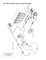
MT-2405F II System Layout - Bypass Plumbing SWITCH BOX RELIEF VALVE CONNECTION SPEED SENSOR SERVO VALVE TANK SHUT-OFF VALVE* THROTTLE VALVE * ITEM NOT INCLUDED WITH SYSTEM AGITATION VALVE SWITCH BOX, BOOM VALVE WIRING, AND BOOM VALVES NOT PROVIDED
Open the catalog to page 7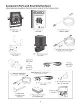
Component Parts and Assembly Hardware Before beginning installation, check the carton contents for the following items: ATIC RATE CONTROL 5’ Hall-effect Flow Sensor Cable with threaded sensor. P/N 13096 MT 1” Electric Servo Valve P/N 14928 FM750 GFN (P/N 11501) 14” Nylon cable ties (10) P/N 12910 or FM750 SS (P/N 10131) Flowmeter A. 5’ Hall-effect Speed/Flow Sensor Cable P/N 13096 Speed Sensor Kit P/N 01531 (1) Including items A-F, below: B. 14” Nylon cable ties (10) P/N 12910 D. Speed sensor mounting bracket P/N 10013
Open the catalog to page 8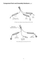
Component Parts and Assembly Hardware (cont) F A Booms 1-5 and Boom Enalbe (no tie) 10’ Power, Servo, Booms Universal Harness Kit P/N 13758 10’ Run/Hold, Speed, Flow Harness P/N 13757 Relief Valve Relay Connectio
Open the catalog to page 9
MT-2405F II System Layout MT-2405F II CONSOLE
Open the catalog to page 10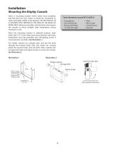
Mounting the Display Console Select a mounting location which seems most workable, and that best fits your needs. It should be con e ient to v n reach and highy vis le to the op r or. DO NOT IN l ib e at STALL IN A POSITION THAT OB TRUCTS THE VIEW OF THE ROAD OR S WORK AREA. Whenever pos i le, avoid lo a ions that ex ose sb c t p the conole to direct sun s light, high tem erure, strong p at chemicals or rain. Tools Needed to Install MT-2405F II • • • • Screwdrivers Set of Wrenches Electric Drill & Bit 12-Volt Test Light Pliers Wire Cutter Center Punch Hammer Place the mounting...
Open the catalog to page 11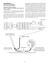
Installation (cont) Locate the power cable on the main wiring harness. See Illustration 3. Connect the RED wire to the contact point you have lo at d. Atach the BLACK wire (ground) to a screw c e t or bolt on the equipment frame. See inset below. (A 4-amp in-line fuse is required for unprotected circuits.) Be sure there is a good metal-to-metal conact. The ter i al con ecors t mn n t have been sup lied for your convenience. You may wish to p sub ti ute other types of con ec ors or make a direct solder s t n t con ecion. In routing cable to con ole, avoid ar as where n t s e the...
Open the catalog to page 12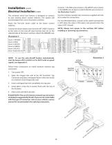
Installation (cont) to boom 1, the red wire to boom 2, the White wire to boom 3, the green wire to boom 4 and the BLACK wire to boom 5. See Illustration 4 and 5. The universal switch box harness is designed to connect to your existing boom control switches. The system will accommodate from one to five boom switches. Use the moisture resistant tap connectors supplied with the kit to make the connections. Electrical Installation (cont) For Two Wire Ball Valves, connect to the switch terminal that is HOT when the valve is ON (open), and ground when the valve is OFF (closed). Route the five-wire...
Open the catalog to page 13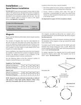
Installation (cont) Speed Sensor Installation PLEASE NOTE: If you have purchased a Vansco radar or other radar or GPS speed sensor, disregard the section on magnetic speed sensors and install the radar or GPS Speed Sensor as described in the instructions packed with the unit. You will need an adapter cable to connect to radar or GPS Speed Sensor, see Appendix I, on page 69. Locations where the sensor may be installed: 1. Non-driven wheel on tractor, vehicle or implement. This is less susceptible to errors resulting from wheel slip. 2. Tractor, vehicle or planter drive shaft. This type of mounting...
Open the catalog to page 14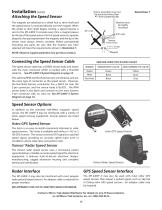
Sensor assembly must not Illustration 7 be mounted more than 45° from perpendicular Installation (cont) Attaching the Speed Sensor The magnets are attached to a wheel hub or drive shaft and the speed sensor is mounted directly over the magnet. When the wheel or drive shaft begins turning, a speed impulse is sent to the MT-2405F II console every time a magnet passes by the tip of the speed sensor. For the speed sensor to operate properly, the spacing between the magnets and the tip of the sensor must always remain constant. Before permanently mounting any parts, be sure that the location you...
Open the catalog to page 15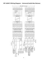
MT-2405F II Wir ng Diagram - Universal Switch Box Harness i MT-2405F II Console BOOM 1 BOOM 2 BOOM 3 BOOM 4 BOOM 5 BOOM ENABLE BATTERY POWER BATTERY GROUND SERVO + SERVO - RELIEF COTROL SPEED POWER SPEED SIGNAL SPEED GROUND RUN/HOLD POWER RUN/HOLD SIGNAL RUN/HOLD GROUND FLOW SIGNAL FLOW POWER FLOW GROUND 10-PIN MERTI-PACK TOWER 10-PIN MERTI-PACK TOWER BLACK TIES (HEAT SHRINK) +VES GROUND BOOM 1 BOOM 2 BOOM 3 BOOM 4 BOOM 5 BOOM ENABLE FLOW RUN/HOLD SPEED
Open the catalog to page 16All Micro-Trak Systems, Inc. catalogs and technical brochures
 flowmeters & servo valves
2 Pages
 ASTRO
ASTRO2 Pages
 MT-2405F™ II 5-BOOM CONTROL
2 Pages
 PLUS SERIES CONTROLLERS
4 Pages
 spraymate II
2 Pages
 astro
astro2 Pages
 FLOWMATE™
1 Page
 TWIN PUMP™
1 Page
 RATEKING™ DUAL PLUS
4 Pages
 3RIVE 3D™
8 Pages
- Irrigation valve
- Control valve
- Hydraulic valve
- On-board multi-purpose instrument
- Tractor multi-purpose instrument
- Digital control system
- Crop input control system
- Irrigation flow meter
- Spraying control system
- Crop input controller
- Seeding control system
- On-board crop input controller
- Tractor crop input controller
- ISO 11783 control system
- Flow-control control system
- Automatic control system
- Magnetic flow meter
- Harvesting control system
- Seed monitoring control system
- Grain dryer control system