
Catalog excerpts

Operators Manual ISOBUS TRAIL-Control Read and follow these operating instructions. Keep these operating instructions in a safe place for later reference.
Open the catalog to page 1
Company details Document Operators Manual Product: ISOBUS TRAIL-Control Document number: 30322332-02-EN As of software version: 2x7g Original language: German Müller-Elektronik GmbH & Co.KG Franz-Kleine-Straße 18 33154 Salzkotten Germany Phone: ++49 (0) 5258 / 9834 - 0 Fax: ++49 (0) 5258 / 9834 - 90 Email: info@mueller-elektronik.de Homepage: http://www.mueller-elektronik.de
Open the catalog to page 2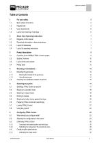
Basic safety instructions Hazard Area User requirements Layout and meaning of warnings About these Operating Instructions Diagrams in this manual Directional information in these instructions Layout of operating instructions Product description Functions of the ISOBUS-TRAIL-Control system System Overview Layout of the work screen Rating plate Mounting the bracket for the gyroscope Using the gyroscope Checking the installation position of sensors Steering in automatic mode Steering in manual mode Steering the trailer device against the slope Preparing TRAIL-Control for road driving Locking...
Open the catalog to page 3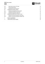
Determining the pulses per 100 meters Using other speed sensors Configuring the reverse driving sensor Configuring the automatic centering Centering when exceeding the maximum speed Centering when switching to manual mode Centering when tapping the centering icon Configuring automatisms when driving in reverse Reaction to the reverse driving signal in manual mode Reaction to the reverse driving signal in automatic mode Technical specifications Technical data for the job computer
Open the catalog to page 4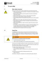
For your safety Basic safety instructions Basic safety instructions Please read the following safety instructions carefully before using the product for the first time. ▪ TRAIL-Control may only be used during field work. The system must be deactivated or switched off on public roads and tracks. ▪ Before you leave the vehicle cab, ensure that all automatic mechanisms are deactivated or manual mode is activated. ▪ Nobody must stay in the proximity of the tractor or trailed implement during operation. ▪ Never remove any safety mechanisms or stickers from the product. ▪ Read the operating...
Open the catalog to page 5
User requirements User requirements ▪ Learn to operate the product in accordance with the instructions. Nobody must operate the product before reading these Operating Instructions. ▪ Please read and carefully observe all safety instructions and warnings contained in these Operating Instructions and in the manuals of any connected vehicles and farm equipment. ▪ If there is anything within these Operating Instructions that you do not understand, please do not hesitate to contact us or your dealer. Müller-Elektronik's Customer Services department will be happy to assist you. Layout and meaning...
Open the catalog to page 6
About these Operating Instructions Diagrams in this manual About these Operating Instructions Diagrams in this manual The screen shots of the software interface are intended to serve as a reference. They help you in finding your way around the software screens. The information shown on the screen depends on various factors: ▪ the type of implement, ▪ the configuration of the implement, ▪ the status of the sensors and actuators. For this reason, the pictures in these operating instructions may show different information than the display on the terminal. All screen shots used in this manual...
Open the catalog to page 7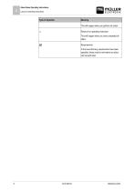
About these Operating Instructions Layout of operating instructions Meaning This will happen when you perform an action. Result of an operating instruction. This will happen when you have completed all steps. Requirements. In the event that any requirements have been specified, these must be met before an action can be performed.
Open the catalog to page 8
Product description Functions of the ISOBUS-TRAIL-Control system Product description Functions of the ISOBUS-TRAIL-Control system ISOBUS-TRAIL-Control serves to steer the trailed implement during field operation. In doing so, it supports the driver in the following ways: ▪ It keeps the trailed implement in the tractor track. ▪ When working on slopes, it steers the trailed implement up the slope so that it does not slip out of the tractor track. The system can control two types of steering systems: ▪ Drawbar steering - These systems only steer the drawbar to the left or right to influence...
Open the catalog to page 9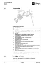
Product description System Overview System Overview Example for a system with drawbar steering Main cable harness Ladder sensor* The ladder sensor serves to detect whether a ladder has been extended on the trailed implement. In this case, TRAIL-Control is blocked and cannot be activated. Proportional valve Angle sensor Determines the angle of a hydraulic cylinder on the drawbar or on a stub axle. For systems with stub axle steering, this sensor is installed on a stub axle. Drawbar locking sensor* Sensor that detects when the drawbar has been locked with a pin. Gyroscope with two brackets...
Open the catalog to page 10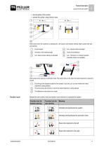
Product description Layout of the work screen ▪ see the status of the system, ▪ operate the system using function icons. Work screen when the implement is standing still. Left: System with drawbar steering; Right: System with stub axle steering Current speed Icon: manual mode is activated Animation of the steering angle Icon: Slope counter-steering is activated Icon: The boom is in transport position. Automatic mode is not possible. Work screen when steering in automatic mode: The tractor drives to the right, the trailed implement is steered to the left. By looking at the displayed position...
Open the catalog to page 11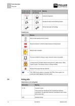
Product description Rating plate Function icon for drawbar steering Function icon for axle steering Activates the slope counter-steering function. Calls up the screens with settings. Possible icons Icon Meaning Slope counter-steering function is active. Shows the direction in which the trailed implement is being steered. Manual mode is activated The boom is folded for driving on roads. Automatic mode is not possible. A locking device is activated: Drawbar locking device or ladder sensor. TRAILControl is locked. The hydraulic valve is not being controlled. Reverse driving signal has been...
Open the catalog to page 12All Müller-Elektronik GmbH & Co. KG catalogs and technical brochures
-
SPRAYDOS
30 Pages
-
S-Box
14 Pages
-
GNSS Receiver AG-200
13 Pages
-
ISOBUS-Joystick PRO
10 Pages
-
ISOBUS Weather Station
2 Pages
-
APP & GO
28 Pages
-
Seeders and Planters
16 Pages
-
SECTION-Control TOP
2 Pages
-
SECTION-Control BOX
2 Pages
-
Plant Protection
20 Pages
-
Fertilization
8 Pages
-
PRODUCT CATALOGUE 2018/2019
64 Pages
-
PRODUCT CATALOGUE 2018
64 Pages
-
Product Catalogue 2016
68 Pages


