
Catalog excerpts

Installation and operating instructions Read and follow these operating instructions. Keep these operating instructions in a safe place for later reference.
Open the catalog to page 1
Company details Document: Installation and operating instructions Product: SPRAYDOS Document number: 30221021-02-EN As of software version: 15.10.13 Original language: German
Open the catalog to page 2
"Number of boom sections" key Copyright Müller-Elektronik GmbH Installation and operating instructions SPRAYDOS (10.2019)
Open the catalog to page 3
"Area / total area" "Spraying fluid l/min" key Boom section main switch Manual/automatic switch Boom section switch Copyright Müller-Elektronik GmbH Installation and operating instructions SPRAYDOS (10.2019)
Open the catalog to page 4
Introduction The SPRAYDOS board computer is a new development on the basis of the well tried and tested SPRAY-Control board computer. The SPRAYDOS has up to 9 boom section switches with a main switch, the manual or automatic regulation of the spray rate and up to 4 hydraulic functions (the long version allows a further 10 hydraulic functions as soon as foam marker and corner nozzles). The current speed and the current spray rate are displayed simultaneously. If an automatic pressure sensor is installed, the pressure is displayed instead of the speed. The speed appears on the display when...
Open the catalog to page 5
Safety instructions The SPRAYDOS is specified exclusively for agricultural use and in wine, fruit and hop growing. The manufacturer takes no responsibility for any installation or application outwith this area. The manufacturer does not accept liability for damage to persons or property resulting from unspecified use. In such cases all risks are the responsibility of the user. Specified implementation also includes adhering to the operation and maintenance requirements stipulated by the manufacturer. Relevant accident prevention regulations as well as other generally recognised safety,...
Open the catalog to page 6
NOTICE This signal word identifies actions which could lead to operational malfunctions if performed incorrectly. These actions require that you operate in a precise and cautious manner in order to produce optimum work results. Safety notice for the subsequent installation of electrical and electronic devices and /or components Present-day agricultural machines are equipped with electronic components and devices, whose function can be affected by electromagnetic emission from other devices. These influences can lead to endangerment for individuals when the following safety measures are not...
Open the catalog to page 7
EC declaration of conformity This product has been manufactured in conformity with the following national and harmonised standards as specified in the current EMV Directive 2004/1008/EG: Dieses Produkt ist in Übereinstimmung mit folgenden nationalen und harmonisierten Normen im Sinne der EMV-Richtlinie 2004/108/EG hergestellt: • EN ISO 14982 Copyright Müller-Elektronik GmbH Installation and operating instructions SPRAYDOS (10.2019
Open the catalog to page 8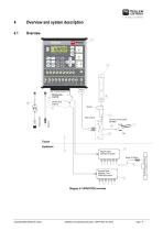
Overview and system description Machine plug manifold Machine plug hydraulic Basic console Continuos current socket DIN 9680 brown Signal socket Tractor Implement Machine signal distributor for sprayer Sensor X (Wheel) Hydraulic signal distributor – long SPRAYDOS version Diagram 4-1 SPRAYDOS overview Copyright Müller-Elektronik GmbH Installation and operating instructions SPRAYDOS (10.2019)
Open the catalog to page 9
SPRAYDOS computer Cap profile rail for mounting the SPRAYDOS Wing screw to secure the computer Bracket S for mounting the cap profile rail Basic console, to be mounted on the tractor cabin. For fitting the bracket with cap profile rail and battery connection. Battery connecting cable for the SPRAYDOS voltage supply, connection to a 12-volt battery. Machine signal distributor Combines the sensor and actuator connections on the machine. Sensor X (wheel) records distance impulses on the trailed field sprayer. Sensor X (cardan shaft / wheel) records speed, impulses on the cardan shaft or front...
Open the catalog to page 10
System description The SPRAYDOS can be installed on the field sprayer as a fully automatic control instrument. The device carries out an area-related control of the spray rate regardless of the current speed, the working width and the pre-set rate. The calculation of the current spray rate, speed, working area, total area, quantity spray as well as the total quantity and the working time is carried out continuously. The device consists of the computer [1] and the console [2-5]. A wheel/cardan speed sensor [9] can be connected directly to SPRAYDOS in order to determine the speed. The...
Open the catalog to page 11
Installation instructions Console and computer The basic console [5] must be mounted vibration-free and electroconductive to the cabin on the driver's right-hand side and within his visual range and reach. The distance to the radio or to the radio antenna should be at least 1 m. Attach the bracket [4] to the tube of the basic console. Mount the cap profile rail [2] on to the bracket. Push the SPRAYDOS computer [1] from above on to the profile and secure using the wing nuts [3]. The console can be swivelled to allow the display to be adjusted to the optimal angle of vision which lies between...
Open the catalog to page 12
WARNING Danger of injury from explosion of the vehicle battery If the battery terminals are loose fitting, starting the vehicle can cause the vehicle battery to overheat. The vehicle battery may then explode. ◦ Always tighten the battery terminals firmly after assembly. CAUTION Damage to the vehicle’s electrical system Switching the polarity of the cables can cause damage to the vehicle’s electrical system. ◦ Pay attention to the polarity of the cable cores and the terminals. > Ensure that the vehicle is switched off. Insert the blue cable core Insert the brown cable core Pinch with a...
Open the catalog to page 13
Sensor X (calculation of the distance) Mounting on four-wheel drive tractors: Mount the hose clamp with a magnet to the cardan shaft. The sensor must point in the direction of the magnets at a distance between 5 – 10 mm. It is to be mounted vibration-free. 5- 10 m m Mounting on tractors without without four-wheel drive: Install the magnets in the wheel shell using V4A screws provided, distributing them evenly over the circumference. Diagram 5-1 Sensor X at the cardan shaft The number of magnets depends on the size of the wheel. The distance travelled from impulse to impulse must not exceed...
Open the catalog to page 14All Müller-Elektronik GmbH & Co. KG catalogs and technical brochures
-
S-Box
14 Pages
-
GNSS Receiver AG-200
13 Pages
-
ISOBUS TRAIL-Control
37 Pages
-
ISOBUS-Joystick PRO
10 Pages
-
ISOBUS Weather Station
2 Pages
-
APP & GO
28 Pages
-
Seeders and Planters
16 Pages
-
SECTION-Control TOP
2 Pages
-
SECTION-Control BOX
2 Pages
-
Plant Protection
20 Pages
-
Fertilization
8 Pages
-
PRODUCT CATALOGUE 2018/2019
64 Pages
-
PRODUCT CATALOGUE 2018
64 Pages
-
Product Catalogue 2016
68 Pages


