- Catalogs
- Summers Mfg. Co.
- Operator’s Manual 34’, 41’, 46’ & 53’ TRAIL-TYPE
Operator’s Manual 34’, 41’, 46’ & 53’ TRAIL-TYPE

Operator’s Manual 34’, 41’, 46’ & 53’ TRAIL-TYPE
The manual provides detailed guidance for operating, assembling, maintaining, and ensuring the safety of Summers Land Roller models 34’, 41’, 46’, and 53’. It highlights the operator's responsibility to adjust the machine as it is not field-ready from the factory.
Summers Manufacturing offers a 36-month warranty covering defects in materials or workmanship, including replacement parts but excluding transportation and indirect costs. Written permission is required for warranty claims.
This section emphasizes understanding safety symbols and practices, such as reading the manual, ensuring safety devices are in place, and avoiding working under the Land Roller. It also specifies minimum tractor requirements for safe operation.
Includes safety practices and step-by-step instructions for setting up the frame, hydraulic systems, and safety lights, stressing the use of suitable lifting devices and personal protective equipment.
Provides operational safety tips and procedures for transitioning the Land Roller between transport and field positions, including initial hookup, field operation, and unhooking from the tractor.
Covers daily and periodic checks, specific instructions for the first four hours of operation, troubleshooting tips, and storage recommendations.
Lists parts with Summers Manufacturing Part Numbers for easy ordering, including diagrams and descriptions for components like the center frame, hitch, and hydraulics.
Advises annual review of the manual and highlights the company's policy of continuous product improvement, providing contact information for obtaining the latest manual versions and replacement decals.
Before servicing or adjusting the Land Roller, ensure it is lowered into field position, blocked to prevent movement, and hydraulic pressure is relieved. Use extreme care during assembly, servicing, or adjustments.
Detailed instructions for installing the main frame roller, hitch, transport frame, wing, and scrapers, emphasizing correct positioning and securing of components.
Instructions for installing hydraulic components and wiring, ensuring slack at pivot points and securing hoses and wires with nylon ties and clamps.
Stresses reading the operator’s manual, verifying safety devices, and ensuring the Land Roller is lowered and blocked before servicing. Advises against allowing riders or children near the machinery.
Includes warranty registration, verifying tractor requirements, and performing initial checks to ensure all fasteners are tight and components are properly greased.
Instructions for safely transitioning the Land Roller from transport to field position, ensuring it is attached to the tractor drawbar and parked on a firm, level surface.
Details various technical components such as pins, zerks, decals, reflectors, and manuals, specifying their types, sizes, and purposes.
Summarizes the company's history from its founding in the 1960s to its expansion and product innovations through the decades.
Describes the range of products including tillage equipment, sprayers, rock pickers, and mounted attachments.
Summers Manufacturing distributes products internationally, reaching markets in North America, Kazakhstan, Russia, and Australia.
Catalog excerpts

Operator’s Manual SUPERROLLER IMPORTANT THE OPERATOR IS RESPONSIBLE FOR ADJUSTING THE MACHINE SINCE MACHINE DOES NOT COME “FIELD READY” FROM FACTORY. CAUTION READ & UNDERSTAND OPERATOR’S MANUAL BEFORE USING MACHINE. See www.summersmfg.com for latest version of all Summers Operator’s Manuals. SUMMERS MANUFACTURING CO., INC. WEB SITE: www.summersmfg.com
Open the catalog to page 1
Warranty Summers warrants only products of its manufacture against operational failure caused by defective materials or workmanship which occur during normal use within 36 months from the date of purchase by the end user from Summers’ dealer. Summers’ obligation is to replace free of charge any part of any product that Summers inspection shows to be defective excluding transportation charges to Devils Lake, ND and return and also excluding all transportation costs from Summers’ dealer to the dealer’s customer and all other costs such as removal and installation expense. Summers shall not be liable...
Open the catalog to page 2
INTRODUCTION This manual provides the following information about your Summers Land Roller. SECTION CONTENTS Section 1 – SAFETY explains important safety precautions and familiarizes the Operator with the decals and their locations. Section 2 – ASSEMBLY includes step by step assembly instructions for your Summers Land Roller. Section 3 – LAND ROLLER OPERATION provides necessary information for the operation and adjustment of the machine. Section 4 – MAINTENANCE covers recommended mechanical maintenance. TROUBLESHOOTING provides a quick reference to solving problems. SPECIFICATIONS lists important...
Open the catalog to page 3
SAFETY-ALERT SYMBOL This symbol is used to denote possible danger and care should be taken to prevent bodily injury. This symbol means: ATTENTION! BECOME ALERT! YOUR SAFETY IS INVOLVED! Definition of each Signal Word used in conjunction with the Safety-Alert symbol. indicates an imminently hazardous situation which, if not avoided, will result in death or serious injury. This signal word is to limited to the most extreme situations. indicates a potentially hazardous situation which, if not avoided, could result in death or serious injury. indicates a potentially hazardous situation which, if...
Open the catalog to page 5
SECTION 1 - SAFETY SAFETY DURING TRANSPORT 1. Ability to safely operate the Summers Superroller is determined by both tractor horsepower and weight. The minimum tractor weight for operating this implement is 20,000 lbs. Minimum tractor engine horsepower is 180. Dual tires or single tires set at maximum width are required for safe operation of Land Roller. 2. ONLY TOW at a safe speed – 20 MPH MAXIMUM. Use caution when making corners and meeting traffic. 3. USE Safety Lights and Safety Chain between tractor drawbar and implement hitch when transporting on public roads. 4. ALWAYS install lift cylinder...
Open the catalog to page 6
SECTION 1 - SAFETY 3. PN 8Z0202 & 8Z0204 – SUPERROLLER ID DECALS 4. PN 8Z0276 – DECAL FOR GENERAL CAUTION
Open the catalog to page 7
SECTION 1 - SAFETY 6. PN 8Z0805 – RED-ORANGE REFLECTOR SAFETY LIGHT OPERATION The Summers Safety Light Kit is equipped with a 7 pin connector which meets SAE J560 specification. To protect 7 pin connector, store in dust cap (8K8067) when not attached to towing vehicle. On most towing vehicles WITHOUT brake lights: Amber lights will turn on with flashers or turn signals. Red lights will turn on with parking, road or field lights. On most towing vehicles WITH brake lights: Amber lights will turn on with flashers, turn signals OR when brake is applied. Red lights will turn on with parking or road...
Open the catalog to page 8
8Z0075 TRANSPORT LOCK DECAL WARNING STICKERS ARE THE SAME ON THE RIGHT SIDE OF MACHINE.
Open the catalog to page 9
GENERAL ASSEMBLY SAFETY PRACTICES 1. READ AND UNDERSTAND Operator’s Manual before assembly of machine. 2. If machine is to be assembled INDOORS, check that exit door is a MINIMUM OF 14’ WIDE and a MINIMUM of tractor height. 3. Reference to “RIGHT” and “LEFT” is determined when machine IS VIEWED FROM THE REAR. 4. Reference to “FORWARD” means TOWARDS THE TRACTOR. 5. Reference to “REAR” means AWAY FROM THE TRACTOR. SAFETY-ALERT SYMBOL This symbol is an alert to the potential for personal injury. This symbol means ATTENTION! BECOME ALERT! YOUR PERSONAL SAFETY
Open the catalog to page 11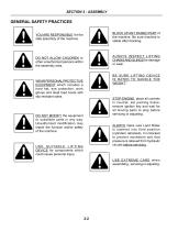
GENERAL SAFETY PRACTICES BLOCK UP ANY RAISED PART of the machine. Be sure machine is stable after blocking. YOU ARE RESPONSIBLE for the safe assembly of the machine. ALWAYS INSPECT LIFTING CHAINS AND SLINGS for damage or wear. DO NOT ALLOW CHILDREN or other unauthorized persons within the assembly area. BE SURE LIFTING DEVICE IS RATED TO HANDLE THE WEIGHT.* WEAR PERSONAL PROTECTIVE EQUIPMENT which includes a hard hat, eye protection, work gloves and steel toed boots with slip resistant soles. STOP ENGINE, place all controls in neutral, set parking brake, remove ignition key and wait for all moving...
Open the catalog to page 12
Main Frame Roller Installation (Instructions for 34’, 41’, 46’ & 53’) (NOTE: 41’ shown in drawings) MF1. Attach 8P7125 to main frame 8P7128 using supplied hardware. MF2. Position 8P4211 on a flat even surface; block the roller to avoid unexpected movement. CAUTION: The 11’ roller weighs 3300 lbs., use extreme care when moving rollers and frame components. NOTE: An H has been stamped onto one end of each roller. Position the center roller with the H to the left. All other rollers should have the H positioned to the center of the machine. MF3. Use a fork lift or Figure 1 crane to position the main...
Open the catalog to page 13
SECTION 2 - ASSEMBLY tighten the set screws. MF6. Before removing the lifting device for the main frame, block the frame in the locations shown in Figure 1, also install blocks under the roller to keep it from rolling. Hitch Installation H1. Position hitch as shown in Figure 2; install the pins and hardware shown in Figure 2. IMPORTANT Always install the pins with the cross hole towards the outside. Pay attention to the orientation of the cross hole in the pin to the cross hole in the bushing on the main frame, only drive the pin in far enough to line up the holes, install the fasteners shown...
Open the catalog to page 14All Summers Mfg. Co. catalogs and technical brochures
 Supercoulter Samurai™
2 Pages
 Operator’s Manual RT8451
46 Pages
 Sprayer Equipment
9 Pages
 Land Rollers / Coil Packers
7 Pages
 Tillage
13 Pages
 S-Tine Cultivators / Harrows
9 Pages
 3RT 2010
1 Page
 Rock Picker
3 Pages
 Mounted Attachments
7 Pages
 Sprayers
7 Pages
 summers_tillage_2014
11 Pages


- Vibro-cultivator
- Vertical tiller
- 2-section disc tiller
- Harrow
- Towed vertical tiller
- Folding vibro-cultivator
- Disc tiller with roller
- Compacting land roller
- Folding harrow
- Chisel field cultivator
- Foldable disc harrow
- Drag harrow
- Offset disc harrow
- Towed field cultivator
- Field cultivator with disk harrow
- Tine harrow
- Depth control disc harrow
- Grading roller
- Smooth roller