
- Catalogs
- Summers Mfg. Co.
- Operator’s Manual COULTER-CHISEL/DISK-CHISEL

Operator’s Manual COULTER-CHISEL/DISK-CHISEL

Operator’s Manual COULTER-CHISEL/DISK-CHISEL
This manual provides detailed guidance on the operation, assembly, maintenance, and troubleshooting of the Summers Coulter-Chisel. It stresses the importance of thoroughly reading the manual before use and recommends an annual review.
Summers Manufacturing Co., Inc. offers a 12-month warranty from the purchase date, covering defects in materials or workmanship. The warranty includes free replacement of defective parts but excludes transportation and installation costs. Claims require written permission and a detailed explanation of defects.
This section outlines safety precautions, emphasizing the understanding of safety symbols and maintaining safety devices. Key practices include stopping the engine before servicing, using hydraulic locks, and ensuring no one is under raised equipment.
Provides step-by-step instructions for assembling the Coulter-Chisel, including hydraulic setup and installation of shanks and coulter gangs. Safety during assembly is emphasized.
Details operational safety, initial hookup, field operation, and transportation procedures. It stresses the importance of safety checks and proper handling during operation.
Covers maintenance schedules, including daily and periodic checks, and storage recommendations to ensure the longevity of the equipment.
Offers a quick reference for solving common problems and lists technical specifications such as dimensions and tire specifications.
Includes detailed parts lists and diagrams for various components of the Coulter-Chisel, aiding in the identification and ordering of replacement parts.
The manual concludes with a reminder of the importance of adhering to safety practices and maintaining the equipment according to the guidelines provided.
Lists various decals with part numbers and their specific locations on the machine, including safety warnings and company identification.
The Summers Safety Light Kit includes a 7-pin connector compliant with SAE J560 specifications. Instructions are provided for light activation with and without brake lights.
Outlines safety practices during assembly, including reading the manual, using personal protective equipment, and ensuring proper lifting techniques.
Provides detailed steps for setting up the main frame, including attaching sections, installing cylinders, and ensuring proper alignment and torque.
Instructions for attaching wings to the center section, installing cylinder brackets, and ensuring proper alignment and securing of components.
Details the assembly of tandem and liftarm components, including bolt specifications and torque requirements.
Instructions for installing wing extensions, gauge wheel supports, and ensuring proper component alignment.
Comprehensive steps for assembling the 40’ machine, including attaching sections, installing cylinders, and ensuring proper alignment and torque.
Instructions for attaching wings to the center section, installing extensions, and ensuring proper alignment and securing of components.
Provides detailed layouts for disk-chisel machinery, emphasizing proper blade placement and dimensions.
Instructions for installing danger, warning, and caution decals, ensuring visibility and correct placement.
Emphasizes operational safety, initial hookup procedures, field operation, and transportation guidelines.
Outlines maintenance safety, daily and periodic maintenance tasks, and storage instructions to prevent rust and damage.
Addresses common problems with potential causes and corrections, including adjustments to depth control cylinders and gauge wheels.
Catalog excerpts

COULTER-CHISEL DISK-CHISEL Operator’s Manual COULTER-CHISEL DISK-CHISEL COULTER-CHISEL DISK-CHISEL IMPORTANT THE OPERATOR IS RESPONSIBLE FOR ADJUSTING THE MACHINE SINCE MACHINE DOES NOT COME “FIELD READY” FROM FACTORY. CAUTION READ & UNDERSTAND OPERATOR’S MANUAL BEFORE USING MACHINE. SUMMERS MANUFACTURING CO., INC. WEB SITE: www.summersmfg.com
Open the catalog to page 1
Warranty Summers warrants only products of its manufacture against operational failure caused by defective materials or workmanship which occur during normal use within 12 months from the date of purchase by the end user from Summers’ dealer. Summers’ obligation is to replace free of charge any part of any product that Summers inspection shows to be defective excluding transportation charges to Maddock, ND or Devils Lake, ND and return and also excluding all transportation costs from Summers’ dealer to the dealer’s customer and all other costs such as removal and installation expense. Summers...
Open the catalog to page 2
This manual provides the following information about your Summers Coulter-Chisel. SECTION CONTENTS Section 1 – SAFETY explains important safety precautions and familiarizes the Operator with the decals and their locations. Section 2 – ASSEMBLY includes step by step assembly instructions. Section 3 – COULTER-CHISEL OPERATION provides necessary information for the operation and adjustment of the machine. Section 4 – MAINTENANCE covers recommended mechanical maintenance. Section 5 – TROUBLESHOOTING provides a quick reference to solving problems. SPECIFICATIONS lists important dimensions, capacities...
Open the catalog to page 3
SECTION 1 - SAFETY SAFETY-ALERT SYMBOL This symbol is used to denote possible danger and care should be taken to prevent bodily injury. This symbol means: ATTENTION! BECOME ALERT! YOUR SAFETY IS INVOLVED! Definition of each Signal Word used in conjunction with the Safety-Alert symbol. DANGER WARNING CAUTION indicates an imminently hazardous situation which, if not avoided, will result in death or serious injury. This signal word is to limited to the most extreme situations. indicates a potentially hazardous situation which, if not avoided, could result in death or serious injury. indicates a potentially...
Open the catalog to page 7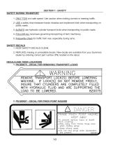
SECTION 1 - SAFETY SAFETY DURING TRANSPORT 1. ONLY TOW at a safe speed. Use caution when making corners or meeting traffic. 2. USE a safety chain between tractor drawbar and implement hitch when transporting on public roads. 3. ALWAYS use hydraulic cylinder transport locks when transporting on public roads. 4. FOLLOW ALL local laws governing transporting of farm machinery. 5. Frequently check for traffic from rear, especially during turns. SAFETY DECALS 1. KEEP SAFETY DECALS CLEAN. 2. REPLACE missing or unreadable decals. New decals are available from your Summers dealer by ordering correct part...
Open the catalog to page 8
SECTION 1 - SAFETY 3. PN 8Z0202 – DECAL FOR COMPANY IDENTIFICATION 4. PN 8Z0276 – DECAL FOR GENERAL CAUTION 5. PN 8Z0340 – DECAL FOR REPHASING CYLINDERS
Open the catalog to page 9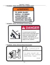
SECTION 1 - SAFETY 6. PN 8Z0342 – DECAL FOR INSTALLING CYLINDER LOCKS 7. PN 8Z0344 – DECAL FOR STAYING CLEAR OF WINGS 8. PN 8Z0346 – DECAL FOR ELECTROCUTION DANGER
Open the catalog to page 10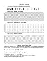
SECTION 1 - SAFETY 9. PN 8Z0348 – DECAL FOR GAUGE WHEEL DEPTH SAFETY LIGHT OPERATION The Summers Safety Light Kit is equipped with a 7 pin connector which meets SAE J560 specification. To protect 7 pin connector, store in dust cap (8K8067) when not attached to towing vehicle. On most towing vehicles WITHOUT brake lights: Amber lights will turn on with flashers or turn signals. Red lights will turn on with parking, road or field lights. On most towing vehicles WITH brake lights: Amber lights will turn on with flashers, turn signals OR when brake is applied. Red lights will turn on with parking or...
Open the catalog to page 11
SECTION 2 – ASSEMBLY INTRODUCTION GENERAL ASSEMBLY SAFETY PRACTICES 1. READ AND UNDERSTAND Operator’s Manual before assembly of machine. 2. Machine should be assembled in a horizontal (field) position only. 3. If machine is to be assembled INDOORS, check that exit door is a MINIMUM OF 22’ WIDE. Height requirement varies up to 16’3”. Shanks may be left off to reduce height and width requirement. 4. Reference to “RIGHT” and “LEFT” is determined when machine IS VIEWED FROM THE REAR. 5. Reference to “FORWARD” means TOWARDS THE TRACTOR. 6. Reference to “REAR” means AWAY FROM THE TRACTOR. SAFETY-ALERT...
Open the catalog to page 13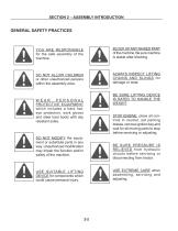
SECTION 2 – ASSEMBLY INTRODUCTION GENERAL SAFETY PRACTICES YOU ARE RESPONSIBLE for the safe assembly of the machine. BLOCK UP ANY RAISED PART of the machine. Be sure machine is stable after blocking. DO NOT ALLOW CHILDREN or other unauthorized persons within the assembly area. ALWAYS INSPECT LIFTING CHAINS AND SLINGS for damage or wear. BE SURE LIFTING DEVICE IS RATED TO HANDLE THE WEIGHT. WEAR PERSONAL PROTECTIVE EQUIPMENT which includes a hard hat, eye protection, work gloves and steel toed boots with slip resistant soles. STOP ENGINE, place all controls in neutral, set parking brakes, remove...
Open the catalog to page 14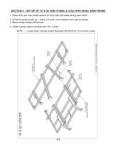
SECTION 2 – SET-UP OF 16’ & 20’ DISK-CHISEL & COULTER-CHISEL MAIN FRAME 1. Place front and rear center section on floor with bolt plates facing each other. 2. ATTACH sections with 24 – 3/4x2-1/4” bolts, lock washers and nuts as shown. 3. Block center frames off the floor. 4. Install cylinder attach brackets with 3/4” u-bolts. NOTE: – Locate Rear Cylinder Attach Brackets (8T4224) 62” from f
Open the catalog to page 15
SECTION 2 – SET-UP OF 16’ & 20’ DISK-CHISEL & COULTER-CHISEL MAIN FRAME 5. Insert eyebolts (8K1683) into each cylinder attach bracket. – Tighten 1-1/2” nuts so the same amount of threads are above top nut on all eyebolts. Insure that cylinder attach holes are aligned when eyebolts are tightened. 6. Liftarms will be centered beneath cylinder attach brackets. – Use 3/4” u-bolts for 4x4 to attach liftarm pivots (8T4100) to frame. – Slide pivot pin (8T3640) through liftarm and liftarm pivots. – Insert 7/16 x 3-1/2” bolt in retaining bolt hole. Secure with lock nut. 7. Install walking tandem assemblies...
Open the catalog to page 16All Summers Mfg. Co. catalogs and technical brochures
 Supercoulter Samurai™
2 Pages
 Operator’s Manual RT8451
46 Pages
 Sprayer Equipment
9 Pages
 Land Rollers / Coil Packers
7 Pages
 Tillage
13 Pages
 S-Tine Cultivators / Harrows
9 Pages
 3RT 2010
1 Page
 Rock Picker
3 Pages
 Mounted Attachments
7 Pages
 Sprayers
7 Pages
 summers_tillage_2014
11 Pages


- Vibro-cultivator
- Vertical tiller
- 2-section disc tiller
- Belt conveyor
- Harrow
- Soil loosener
- Grain conveyor
- Towed vertical tiller
- Folding vibro-cultivator
- Disc tiller with roller
- Inclined conveyor
- Mobile conveyor
- Compacting land roller
- Folding harrow
- Chisel field cultivator
- Towed field cultivator
- Foldable disc harrow
- Offset disc harrow
- Drag harrow
- 5-shank sub-soiler