- Catalogs
- Summers Mfg. Co.
- Operator’s Manual - DK2610 & DT2510
Operator’s Manual - DK2610 & DT2510

Operator’s Manual - DK2610 & DT2510
This manual is for the Diamond Disk (DK2610) and 2510 DT (DT2510) models by Summers Manufacturing Co., Inc. It includes sections on Safety, Operation & Maintenance, Troubleshooting, and Parts. The manual emphasizes the importance of reading and understanding the instructions for safe operation and maintenance.
The safety section highlights the importance of understanding safety symbols and following safe practices. Key points include reading the manual, ensuring safety devices are in place, and following proper procedures during transportation. Safety decals are used to indicate various levels of hazards, with specific colors denoting the severity.
This section covers connecting the implement, field operation, and transportation. It provides detailed instructions on the use of the rear coulter gang and proper storage practices. Troubleshooting tips and proper bolt use are also included to ensure efficient operation.
The parts section provides a comprehensive breakdown of the machine's components, including hitch, caster wheel hitch, main frame, hydraulics, and various assemblies. Each part is referenced with a specific Summers Manufacturing part number for easy ordering.
Summers Manufacturing offers a 36-month warranty against operational failure due to defective materials or workmanship. The warranty covers replacement parts but excludes transportation and other associated costs. Written permission is required for warranty claims.
For further assistance, contact Summers Manufacturing Co., Inc. at their Devils Lake, ND location or visit their website for the latest manuals.
Safety awareness is crucial, especially if safety signs are damaged or missing. New signs should be obtained from authorized dealers. Key safety decals include transport lock, pinch point, and general machine caution decals, each with specific warnings and instructions to prevent injury.
Maintenance safety involves personal protective equipment, avoiding unauthorized modifications, and ensuring all safety devices are in place. Hydraulic systems should be handled with care, and lifting devices must be rated for the weight they handle.
For disk lift hydraulic cylinders, ensure air is purged by maintaining hydraulic pressure. Wing lift cylinders require oil charging before operation. Safety lock pins should be removed before lowering wings.
Before field operation, remove safety locks and level the disk. Adjustments should be made with no pressure in the cylinders. Depth settings vary by machine size, and rear coulter gangs require specific hydraulic pressure settings.
Transporting involves securing safety locks and using safety chains. Speed should not exceed 20 mph, and safety lights should be used. For storage, clean the machine, check for damage, grease all zerks, and protect parts from rust.
Regular maintenance includes greasing gang bearings every 20 hours and checking wheel bolts. Tire inflation pressures are specified for different tire sizes. Seasonal maintenance involves cleaning and repacking wheel bearings.
Common problems such as trash buildup can be addressed by adjusting components or installing options like the Coulter Option.
Seal Support Installation: Use two Seal Supports (8R6927) and press each onto the spindle 5/8" past the inner bearing retaining shoulder. Apply a thin layer of grease to the counterface surface during seal installation.
Seal Counterface Installation: Press the Seal Counterface (8R6924) into the hub until the shoulder contacts the hub.
V-Seal Installation: Stretch the V-Seal (8R6923) over the Seal Support until it is seated against the back shoulder.
Hubodometer Installation: Attach the Hub Odometer to the gang nut using a 3/8” x 4-1/2” bolt, flat washers, and lock nut. Ensure the bracket is centered and spot weld at specified locations. The Hub Odometer is calibrated at 359 revolutions per acre. Use the provided conversion chart for different implement widths.
The document lists various nuts, lockwashers, washers, pins, and other hardware components with specific dimensions and grades.
Summers Manufacturing Co., Inc. was founded in 1965 by Harley Summers. The company initially produced truck and pickup hoists and expanded into manufacturing agricultural equipment such as harrows and sprayers.
Key milestones include the introduction of the Agri-sprayer in 1977, the acquisition of Crown rockpickers in 1980, and the launch of the Supercoulter in 2000.
Summers Manufacturing distributes its products to dealers and distributors across North America and internationally, including markets in Kazakhstan, Russia, and Australia.
For more information, Summers Manufacturing can be contacted at 1-800-732-4347 or through their website at www.summersmfg.com.
Catalog excerpts

Operator’s Manual (Diamond Disk & 2510 DT Series) THE OPERATOR IS RESPONSIBLE FOR ADJUSTING THE MACHINE SINCE MACHINE DOES NOT COME “FIELD READY” FROM FACTORY. CAUTION READ & UNDERSTAND OPERATOR’S MANUAL BEFORE USING MACHINE. See www.summersmfg.com for latest version of all Summers Operator’s Manuals. SUMMERS MANUFACTURING CO., INC. WEB SITE: www.summersmfg.com DEVILS LAKE, NORTH DAKOTA 58301 8Z1090
Open the catalog to page 1
FORWARD Preface This manual is intended for use with Diamond Disk (DK2610) or 2510 DT (DT2510) for Summers® Manufacturing Company, Inc. This book is composed of these basic sections: Safety, Operation & Maintenance, Troubleshooting and Parts. The safety section provides complete instructions for the proper safe operation of a Summers Mfg. product. The Operation & Maintenance section provides information for the proper operation and maintenance. A complete parts breakdown is provided in the Parts section. Parts are referenced in each drawing with the Summers Manufacturing part number. Use this...
Open the catalog to page 5
Summers warrants only products of its manufacture against operational failure caused by defective materials or workmanship which occur during normal use within 36 months from the date by the end user from Summers’ dealer. Summers’ obligation is to replace, free of charge, any part of the product that Summers inspection shows to be defective excluding transportation charges to Devils Lake, ND and return and also excluding all transportation costs from Summers’ dealer to the dealer’s customer and all other costs, such as removal and installation expense. Summers shall not be liable for loss of...
Open the catalog to page 6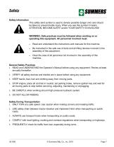
Safety Safety Information This safety alert symbol is used to denote possible danger and care should be taken to prevent bodily injury. When you see this symbol it means ATTENTION, BECOME ALERT! and/or YOUR SAFETY IS INVOLVED! WARNING: Safe practices must be followed when working on or operating this equipment. All personnel involved must: • Read and understand the instructions and manuals for this machine. • Be instructed in the safe use of tools and all lifting devices involved in the assembly of this equipment. • Clear the area of all personnel not involved in the assembly of this machine....
Open the catalog to page 7
Safety Decals DANGER WARNING CAUTION Indicates an immediate hazardous situation that will result in death or serious injury. The color associated with Danger is RED. Indicates a potentially hazardous situation that could result in death or serious injury. The color associated with Warning is ORANGE. Indicates a potentially hazardous situation that may result in minor or moderate injury. It may also be used to alert against unsafe practices. The color associated with Caution is YELLOW. The Notice decals and statements in this manual are to inform the operator of the correct fluids or operational...
Open the catalog to page 8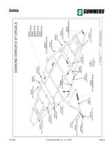
SERIAL # PLATE GENERAL CAUTION ELECTROCUTION DANGER WING DANGER AMBER REFL GREASE DECAL PINCH POINT DANGER TRANS LOCK WING DANGER Place rephasing cylinders decal on the 6 x 10 cylinder. GREASE DECAL AMBER REFL WING DANGER PINCH POINT DANGER RED-ORANGE REFL RED-ORANGE REFL PINCH POINT DANGER WING DANGER
Open the catalog to page 9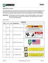
Safety Decal Locations The types of safety signs and locations on the equipment are shown in the illustrations below. Good safety requires that you familiarize yourself with the various safety signs, the type of WARNING and the area or particular function related to that area, that requires your SAFETY AWARENESS. IMPORTANT: If Safety Signs have been damaged, removed, become illegible or parts replaced without safety signs, new signs must be applied. New safety signs are available from your authorized dealer. Safety Decals TRANSPORT LOCK DECAL WARNING REMOVE TRANSPORT LOCK(S) BEFORE LOWERING MACHINE....
Open the catalog to page 10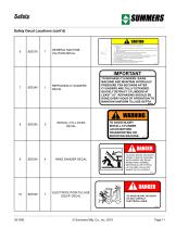
Safety Decal Locations (cont’d) GENERAL MACHINE CAUTION DECAL 1. Read and understand Operator’s Manual before using machine. 2. For Sprayers: a. Read and follow chemical manufacturers’ WARNINGS, instructions and procedures before using. b. Use recommended personal protective equipment to reduce or eliminate chemical contact. c. Never run pump dry. 3. Verify all safety devices and shields are in place before using machine. 4. Keep hands, feet, hair and clothing away from moving parts. 5. Stop engine, place all controls in neutral, set parking brakes, remove ignition key and wait for all moving...
Open the catalog to page 11
Safety Decal Locations (cont’d) IMPORTANT GANG BEARING GREASE DECAL REFLECTOR - YELLOW ADHESIVE BACKED REFLECTOR - REDORANGE ADHESIVE BACKED REFLECTOR - RED ADHESIVE BACKED *GREASE GANG BEARINGS EVERY 20 HOURS.* GREASE AT MID DAY OR END OF DAY WHEN BEARINGS ARE AT OPERATING TEMPERATURE. ADD 3 STROKES OF CHEVRON ULTRA-DUTY EP NLGI 2 OR EQUIVALENT. ROTATE GANG 2 TO 3 REVOLUTIONS. ADD THREE MORE STROKES. GREASE ALL ZERKS ON MACHINE BEFORE EXTENDED STORAGE PERIOD. 8Z0350 DK/DT DECAL Safety Light Operation Figure 1 The Summers Safety Light Kit is equipped with a 7 pin connector which meets SAE J560...
Open the catalog to page 12
General Maintenance Safety Practices NOTE: Read the entire section before beginning work. Before You Begin • YOU ARE RESPONSIBLE for the safe maintenance of the equpment. • DO NOT ALLOW CHILDREN or other unauthorized persons within the equipment’s operational area. • WEAR PERSONAL PROTECTIVE EQUIPMENT which includes a hard hat, eye protection, work gloves and steel toed boots with slip resistant soles. • DO NOT MODIFY the equipment or substitute parts in any way. Unauthorized modifications may impair the function and/or safety of the machine. • USE SUITABLE LIFTING DEVICE for components which...
Open the catalog to page 13
START-UP AND HYDRAULIC OPERATION INITIAL START UP PROCEDURE FOR DISK LIFT HYDRAULIC CYLINDERS This disk has a Master-Slave Hydraulic Lift System. Fully extend hydraulic cylinders and maintain hydraulic pressure for 30 seconds to insure all air is purged from system. See diagram on previous page. NOTE: As oil is pumped into the base end of master cylinder, oil is forced out of the rod end into the base end of each slave cylinder. To compensate for the smaller volume of oil in the rod end of the master cylinder, each slave cylinder is 1/2” smaller in diameter. When cylinders are fully extended,...
Open the catalog to page 15All Summers Mfg. Co. catalogs and technical brochures
 Supercoulter Samurai™
2 Pages
 Operator’s Manual RT8451
46 Pages
 Sprayer Equipment
9 Pages
 Land Rollers / Coil Packers
7 Pages
 Tillage
13 Pages
 S-Tine Cultivators / Harrows
9 Pages
 3RT 2010
1 Page
 Rock Picker
3 Pages
 Mounted Attachments
7 Pages
 Sprayers
7 Pages
 summers_tillage_2014
11 Pages


- Vibro-cultivator
- Vertical tiller
- 2-section disc tiller
- Towed vertical tiller
- Folding vibro-cultivator
- Disc tiller with roller
- Compacting land roller
- Folding harrow
- Chisel field cultivator
- Foldable disc harrow
- Drag harrow
- Offset disc harrow
- Towed field cultivator
- Field cultivator with disk harrow
- Tine harrow
- Depth control disc harrow
- Grading roller
- Stone picker
- Smooth roller