- Catalogs
- Summers Mfg. Co.
- Operator’s Manual DT9530 & DK9630
Operator’s Manual DT9530 & DK9630

Operator’s Manual DT9530 & DK9630
The operator's manual for the DT9530 and DK9630 disk models by Summers Manufacturing Co., Inc. provides crucial information on safety, assembly, operation, maintenance, and parts. It highlights the operator's responsibility to adjust the machine as it is not field-ready from the factory.
Summers Manufacturing offers a 36-month warranty against operational failure due to defective materials or workmanship. The warranty covers replacement parts but excludes transportation and other costs. Written permission is required for claims.
The manual is divided into four sections: Safety, Assembly, Operation and Maintenance, and Parts. It includes detailed instructions and guidelines, emphasizing the importance of understanding the manual before use.
This section covers general safety practices, transport safety, and the importance of maintaining safety decals.
Detailed assembly instructions are provided, emphasizing safety and the use of suitable lifting devices.
Includes start-up procedures, hydraulic operation, field operation guidelines, troubleshooting tips, and storage recommendations.
Provides a detailed parts list with references for easy ordering.
The manual is a comprehensive guide for the safe and efficient use of the disk models, stressing the importance of familiarization with all sections.
Section 2 details the assembly of hydraulic systems, including parts descriptions and specifications. It covers configurations for closed and open-center hydraulic systems.
Section 3 outlines start-up procedures for hydraulic cylinders, emphasizing safety precautions.
Recommends checking bolts, grease fittings, and tire pressure before operation.
Includes greasing schedules, tire inflation recommendations, field operation adjustments, and troubleshooting common issues.
Details the company's expansion and product development from 1992 to 2015, highlighting new products and facility expansions.
Summers distributes products to dealers and distributors in the USA and internationally.
The product line includes tillage equipment, land rollers, sprayers, cultivators, rock pickers, and mounted attachments.
Catalog excerpts

Operator’s Manual DT9530 & DK9630 DISK MODELS IMPORTANT THE OPERATOR IS RESPONSIBLE FOR ADJUSTING THE MACHINE SINCE MACHINE DOES NOT COME “FIELD READY” FROM FACTORY. CAUTION READ & UNDERSTAND OPERATOR’S MANUAL BEFORE USING MACHINE. See www.summersmfg.com for latest version of all Summers Operator’s Manuals. SUMMERS MANUFACTURING CO., INC. WEB SITE: www.summersmfg.com DEVILS LAKE, NORTH DAKOTA 58301 8Z1091
Open the catalog to page 1
Warranty Summers warrants only products of its manufacture against operational failure caused by defective materials or workmanship which occur during normal use within 36 months from the date of purchase by the end user from Summers’ dealer. Summers’ obligation is to replace free of charge any part of any product that Summers inspection shows to be defective excluding transportation charges to Devils Lake, ND and return and also excluding all transportation costs from Summers’ dealer to the dealer’s customer and all other costs such as removal and installation expense. Summers shall not be liable...
Open the catalog to page 2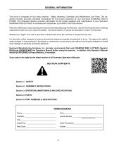
GENERAL INFORMATION This book is composed of four basic sections: Safety, Assembly, Operation and Maintenance, and Parts. The Assembly Section provides complete instructions for the proper assembly of your Summers DIAMOND DISK & DT9530. The Operation Section provides information for the proper operation and maintenance of your Summers DIAMOND DISK & DT9530. A complete parts breakdown is provided in the Parts Section. Parts are referenced in each drawing with the Summers Manufacturing Part Number. Use this Part Number when ordering replacement parts from your Summers dealer. See back section of...
Open the catalog to page 3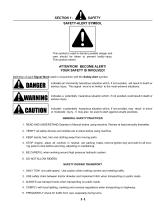
SAFETY-ALERT SYMBOL This symbol is used to denote possible danger and care should be taken to prevent bodily injury. This symbol means: ATTENTION! BECOME ALERT! YOUR SAFETY IS INVOLVED! Definition of each Signal Word used in conjunction with the Safety-Alert symbol. indicates an imminently hazardous situation which, if not avoided, will result in death or serious injury. This signal word is to limited to the most extreme situations. indicates a potentially hazardous situation which, if not avoided, could result in death or serious injury. indicates a potentially hazardous situation which, if...
Open the catalog to page 5
SAFETY DECALS A. KEEP SAFETY DECALS CLEAN. B. REPLACE missing or unreadable decals. New decals are available from your Summers dealer by ordering correct part number (PN) located on decal. C. Locations shown on Page 1-6. 1. TRANSPORT LOCK WARNING DECAL (PN 8Z0075) WARNING REMOVE TRANSPORT LOCK(S) BEFORE LOWERING MACHINE. IF LOCK(S) DO NOT REMOVE FREELY, INSURE THAT CYLINDERS ARE COMPLETELY FILLED WITH HYDRAULIC FLUID AND ARE SUPPORTING THE LOAD TO BE LOWERED. 8Z0075 2. GENERAL CAUTION DECAL (PN 8Z0276) CAUTION 1. Read and understand Operator’s Manual before using machine. 2. For Sprayers: a....
Open the catalog to page 6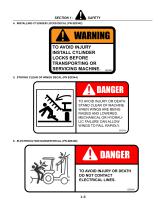
4. INSTALLING CYLINDER LOCKS DECAL (PN 8Z0342) WARNING TO AVOID INJURY INSTALL CYLINDER LOCKS BEFORE TRANSPORTING OR SERVICING MACHINE. 5. STAYING CLEAR OF WINGS DECAL (PN 8Z0344) DANGER TO AVOID INJURY OR DEATH STAND CLEAR OF MACHINE WHEN WINGS ARE BEING RAISED AND LOWERED. MECHANICAL OR HYDRAULIC FAILURE CAN ALLOW WINGS TO FALL RAPIDLY. 8Z0344 6. ELECTROCUTION DANGER DECAL (PN 8Z0346) DANGER TO AVOID INJURY OR DEATH DO NOT CONTACT ELECTRICAL LINES. 8Z0346
Open the catalog to page 7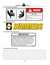
7. PINCH POINT DECAL (PN 8Z0087) DANGER FRAME PINCH POINT HAZARD KEEP AWAY To prevent serious injury or death from crushing: • Stay away from frame hinge area when folding wings. • Keep others away. • Do not fold wings when bystanders are present. 8Z0087 9. GANG BEARING GREASE (PN 8Z0350) IMPORTANT *GREASE GANG BEARINGS EVERY 20 HOURS.* GREASE AT MID DAY OR END OF DAY WHEN BEARINGS ARE AT OPERATING TEMPERATURE. ADD 3 STROKES OF CHEVRON ULTRA-DUTY EP NLGI 2 OR EQUIVALENT. ROTATE GANG 2 TO 3 REVOLUTIONS. ADD THREE MORE STROKES. GREASE ALL ZERKS ON MACHINE BEFORE EXTENDED STORAGE PERIOD. 8Z0350...
Open the catalog to page 8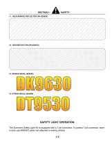
SAFETY LIGHT OPERATION The Summers Safety Light Kit is equipped with a 7 pin connector. To protect 7 pin connector, store in dust cap (8K8067) when not attached to towing vehicle. 1-5
Open the catalog to page 9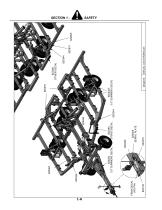
DECAL LOCATIONS.iam
Open the catalog to page 10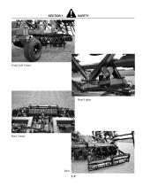
Front Left Caster Rear Lights Rear Center
Open the catalog to page 11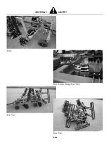
Rear Coulter Gang Hyd. Valve Side View
Open the catalog to page 12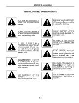
GENERAL ASSEMBLY SAFETY PRACTICES YOU ARE RESPONSIBLE for the safe assembly of the machine. BLOCK UP ANY RAISED PART of the machine. Be sure machine is stable after blocking. DO NOT ALLOW CHILDREN or other unauthorized persons within the assembly area. ALWAYS INSPECT LIFTING CHAINS AND SLINGS for damage or wear. BE SURE LIFTING DEVICE IS RATED TO HANDLE THE WEIGHT. WEAR PERSONAL PROTECTIVE EQUIPMENT which includes a hard hat, eye protection, work gloves and steel toed boots with slip resistant soles. STOP ENGINE, place all controls in neutral, set parking brakes, remove ignition key and wait...
Open the catalog to page 13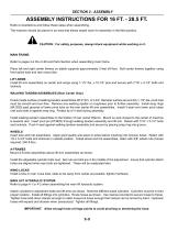
ASSEMBLY INSTRUCTIONS FOR 16 FT. - 28.5 FT. Refer to illustrations and follow these steps when assembling. The machine should be placed in an area that allows ample room for assembly in the field position. CAUTION: For safety purposes, always block equipment while working on it. MAIN FRAME: Refer to pages 2-4 thru 2-28 and Parts Section when assembling main frame. Place left and right center frames on stable supports approximately 3 feet off floor. Bolt center frames together using front splice tube and rear cross tube. LIFT ARMS Install lift arm assemblies on center and wings using 1-1/2” dia....
Open the catalog to page 14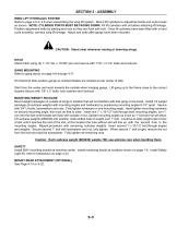
WING LIFT HYDRAULIC SYSTEM Refer to page 4-5 or 4-6 when assembling the wing lift system. Mount lift cylinders to adjustment bolts and route hoses as shown. NOTE: CYLINDER PORTS MUST BE FACING DOWN. Fill lift cylinders with oil before attaching lift linkage. Position adjustment bolts by starting end nuts so they are flush with bolt. Once lift cylinders have been filled with oil and cycle smoothly, connect wing lift linkage. Adjust eye bolts after gangs have been mounted. CAUTION: Stand clear whenever raising or lowering wings. HITCH Attach hitch using (2) 1-1/2” dia. x 10-5/8” pins and secure...
Open the catalog to page 15All Summers Mfg. Co. catalogs and technical brochures
 Supercoulter Samurai™
2 Pages
 Operator’s Manual RT8451
46 Pages
 Sprayer Equipment
9 Pages
 Land Rollers / Coil Packers
7 Pages
 Tillage
13 Pages
 S-Tine Cultivators / Harrows
9 Pages
 3RT 2010
1 Page
 Rock Picker
3 Pages
 Mounted Attachments
7 Pages
 Sprayers
7 Pages
 summers_tillage_2014
11 Pages


- Vibro-cultivator
- Vertical tiller
- 2-section disc tiller
- Harrow
- Towed vertical tiller
- Folding vibro-cultivator
- Disc tiller with roller
- Compacting land roller
- Folding harrow
- Chisel field cultivator
- Foldable disc harrow
- Drag harrow
- Offset disc harrow
- Towed field cultivator
- Field cultivator with disk harrow
- Tine harrow
- Depth control disc harrow
- Grading roller
- Smooth roller