MH200

MH200
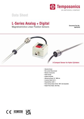
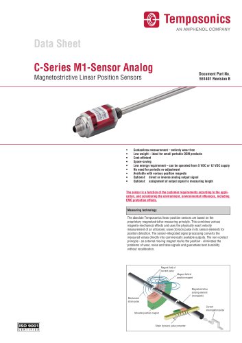
Temposonics® MH-Series sensors are designed for mobile machinery, utilizing magnetostrictive technology for non-contact, wear-free linear position sensing. They are robust against vibration, shock, dust, and electromagnetic disturbances, suitable for harsh environments.
- Stroke range: up to 5000 mm
- Linearity: < 0.04% F.S.
- Resolution: typically 0.5 mm
- Operating pressures: up to 320 bar
- Output signals: Analog (VDC/mA), Bus protocols (CANopen, SAE J1939)
The M12 connector system is designed for easy installation, meeting IP69K standards for water and dust resistance, allowing quick installation without soldering or crimping.
Sensors are available with stroke ranges from 2520 to 5000 mm and wire lengths from 60 to 240 mm, featuring a robust flange housing and a pressure pipe.
Sensors can be installed from either the rod or head side of a hydraulic cylinder, requiring attention to cylinder design and O-rings for sealing.
Available with or without support tubes, in various dimensions and materials for different applications.
Operating temperatures range from -40 to +105 °C, withstanding pressures up to 550 bar, tested for shock and vibration resistance per IEC standards.
Offers analog and digital outputs, with specific pin assignments for M12 connectors, compatible with 12/24 VDC power supplies.
Tested for compliance with agricultural, construction, and EMC standards, constructed from stainless steel and durable materials for longevity.
Detailed data for analog and digital models, stroke range 2520 to 5000 mm, resolution 0.5 mm for position, 1 mm/s for velocity, supporting CANopen and SAE J1939 protocols.
Includes position magnets, M12 flange test kits, and software for digital models, with part numbers for ordering.
Contact details for Temposonics offices in the US, Germany, Italy, France, UK, Scandinavia, China, and Japan.
Catalog excerpts
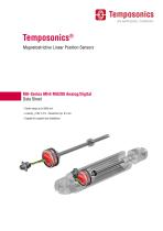
Temposonics® Magnetostrictive Linear Position Sensors - Capable for support tube installation
Open the catalog to page 1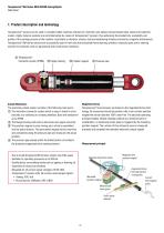
Temposonics® MH-Series MH4 MH200 Analog/Digital Data Sheet 1. Product description and technology Temposonics ® sensors can be used in versatile mobile machines without any restriction and replace contact-based linear sensors like potentiometers. Highly dynamic systems are controlled safely by means of Temposonics ® sensors, thus enhancing the productivity, availability and quality of the working process of the machine. Insensitive to vibration, shocks, dust and weathering influence and electro-magnetic disturbances. Temposonics ® MH Series sensors are successfully used in front axle and articulated...
Open the catalog to page 2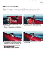
Temposonics® MH-Series MH4 MH200 Analog/Digital Data Sheet 2. Temposonics® connector system M12 Temposonics presents the innovative connector system for Temposonics® MH-Series The Temposonics® Connector System meets the highest protection requirements important for a harsh environment in mobile hydraulic applications. Protection type IP69K performs water and dust proof. In addition it is even resistive against high pressure water cleaning. The MH sensor is delivered by Temposonics together with the The connector insert is taken out of the cylinder through a bore hole. The flange can easily be...
Open the catalog to page 3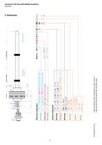
Wire length Please see detailed model configuration on page 13 and 15. Please see document 551308 for MH with cable version. Electrical configurations Stroke range Form factor Mechanical configurations Temposonics® MH-Series MH4 MH200 Analog
Open the catalog to page 4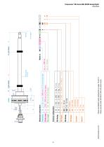
Stroke range Wire length Please see detailed model configuration on page 13 and 15. Please see document 551308 for MH with cable version Electrical configurations Form factor Mechanical configurations Temposonics® MH-Series MH4 MH200 Analog/D
Open the catalog to page 5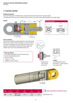
Temposonics® MH-Series MH4 MH200 Analog/Digital Data Sheet 4. In Cylinder assembly Mechanical installation The robust Temposonics® model MH sensor is designed for direct stroke measurement in hydraulic cylinders. The Temposonics® MH sensor can be installed from the head side or the rod side of the cylinder depending on the cylinder design. 30 Sensor installation The method of installation is entirely dependent on the cylinder design. While the most common method of installation is from the rod side of the cylinder, an installation from the head side of the cylinder is also possible. In both installation...
Open the catalog to page 6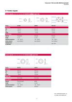
Temposonics® MH-Series MH4 MH200 Analog/Digital Data Sheet Position magnets (please order separately) for installation without support tube Fastening torque for M4 screws Position magnets (please order separately) for installation with support tube Support tube Material PA ferrite coated *max. mechanical burden, e.g. by circlip, lock washers etc.
Open the catalog to page 7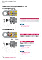
Temposonics® MH-Series MH4 MH200 Analog/Digital Data Sheet Spacer Spacer Aluminum) Aluminum) S=ODM x 5 x IDM 4.2.2 Installation with support tube Spacer Spacer Aluminum) Aluminum) S=ODM x 5 x IDM Spacers, washers, pretension parts etc. are not part of MTS shipment! Stroke range Support tube Piston rod drilling Magnet Spacers, washers, pretension parts etc. are not part of MTS shipment! For correct sensor installation and technical support please contact our application team
Open the catalog to page 8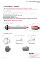
Data Sheet Please note that the support tube assembly and the adapter accessories is a proposal by Temposonics.For further design information please consult Temposonics application engineering who will consult and clarify as required.Please pay attention to: • Support tube adapters must enable oilflow to get rid of air when cylinder gets oil filled • Support tubes material is stainless steel 1.4301 (AISI 304) or 1.4305 (AISI 303). If machining is conducted on stainless steel support tubes please make sure it does not induce magnetic properties to the material. • Nut M8 to tighten with max. 4...
Open the catalog to page 9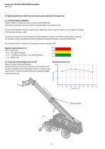
Temposonics® MH-Series MH4 MH200 Analog/Digital Data Sheet 4.4 Operating conditions and load limits considering a sensor installation with support tube. 4.4.1 Vibration Ratings on Machines Vibration ratings for machines are shown in the EU directive 2002/44/EC. Real effective accelerations and forces within the hydraulic cylinder may exceed this level. For the cylinder installation requiring a support tube an applied load collective has been defined in order to approve the design for the resonance frequency range. Considering the results out of the load collective the operating grade for pressure...
Open the catalog to page 10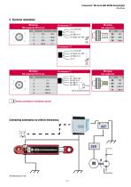
MH AnalogPIN assignment M12 (4 pin) Pin assignment “G” Temposonics® MH-Series MH4 MH200 Analog/Digital Data Sheet MH Analog wire assignment Color Signal MH DigitalPIN assignment M12 (5 pin) Pin assignment “F” MH Digital wire assignment Pin Color Signal Please pay attention to installation manual! Connecting schematics on vehicle electronics:
Open the catalog to page 11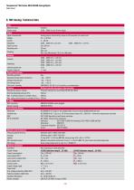
Data Sheet
Open the catalog to page 12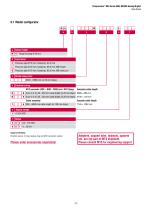
Temposonics® MH-Series MH4 MH200 Analog/Digital Data Sheet Form factor Pressure pipe Ø 10 mm, Damping: 63.5 mm Pressure pipe Ø 10 mm, Damping: 69.5 mm, M6 female Q Pressure pipe Ø 10 mm, Damping: 85.5 mm, M8 male port c Stroke range (mm) 2520…5000 mm (in 20 mm steps) d Electrical wiring M12 connector (VDC – GND – SIGN) incl. M12 flange Examples cable length G 4 pin (1-3-4), 60…240 mm cable length (in 20 mm steps) N08G = 080 mm H 4 pin (1-3-2), 60…240 mm cable length (in 20 mm steps) N10H = 100 mm Cable assembly A 300…9000 mm cable length (in 100 mm steps) Supply voltage Example cable length T10A...
Open the catalog to page 13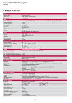
Data Sheet
Open the catalog to page 14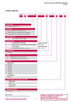
Data Sheet |~^| Pressure pipe 0 10 mm, Damping: 63.5 mm L Pressure pipe 0 10 mm, Damping: 69.5 mm, M6 female Q I Pressure pipe 0 10 mm, Damping: 85.5 mm, M8 male N F 5 pin (2-3-4-5), 60.240 mm cable length (in 20 mm steps) N08F = 080mm Cable assembly Example cable length T A 300.9000 mm cable length (in 100 mm steps) T10A = 1000 mm C 0 1 I CANopen cycle time 1 ms (default setting) J 0 1 SAE J1939 cycle time 20 ms (default setting) 0 1000 kbit/s [T] 800 kbit/s [T| 500 kbit/s [T] 250 kbit/s [T| 125 kbit/s [T] 50 kbit/s Position sensor, O-ring, backup-ring and M12 connector system Please order accessories...
Open the catalog to page 15All Temposonics GmbH & Co. KG catalogs and technical brochures
 TempoLink® smart assistant
7 Pages
 HIGH PRESSURE HOUSING (HPH)
7 Pages
 T-Series – TH CANbus
15 Pages
 T-Series – TH SSI
15 Pages
 T-Series – TH Analog
14 Pages
 GB with threaded flange Analo
10 Pages
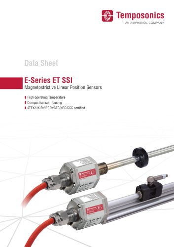 E-Series ET SSI
11 Pages
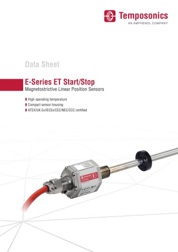 E-Series ET Start/Stop
8 Pages
 E-Series ET Analog
11 Pages
 R-Series V RM5 EtherNet/IP™
11 Pages
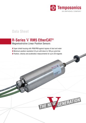 R-Series V RM5 EtherCAT®
11 Pages
 R-Series V RM5 POWERLINK
11 Pages
 R-Series V RM5 Analog
12 Pages
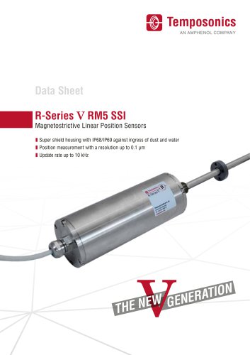 R-Series V RM5 SSI
12 Pages
 LD
LD8 Pages
 C M1
C M14 Pages
 GTE
GTE7 Pages
 V RP5
V RP510 Pages