
Catalog excerpts
VINCKE HYDRAULICS Variable Displacement Piston Pumps
Open the catalog to page 1
your Hydraulic Brand
Open the catalog to page 2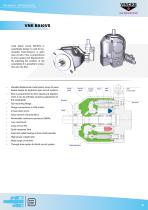
your Hydraulic Brand Axial piston pump BA10VS in swashplate design is used for hydrostatic transmissions in open loop circuits. Flow is proportional to drive speed and displacement. By adjusting the position of the swashplate it is possible to smoothly vary the flow. Variable displacement axial piston pump of swashplate design for hydraulic open circuit systems. Flow is proportional to drive speed and displacement. It can be infinitely varied by adjustment of the swashplate. Flange connections to SAE metric. 2 Case drain ports. Good suction characteristics. Permissible continuous pressure...
Open the catalog to page 3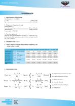
your Hydraulic Brand Weight (Without fluids) Flow qv= Torque T= Power P= Vg= Displacement per revolution in in3 (cm3) ∆p= Differential pressure in psi (bar) n = Speed in rpm (min-1) ηv= Volumetric efficiency ηmh= Mechanical-hydraulic e
Open the catalog to page 4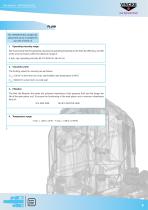
your Hydraulic Brand FLUID The VNKBA10VSO variable displacement pump is suitable for use with mineral oil. 1. Operating viscosity range We recommend that the operating viscosity (at operating temperature) for both the efficiency and life of the unit, be chosen within the optimum range of V opt= opt. operating viscosity 80...170 SUS (16...36 mm2/s) 2. Viscosity Limits The limiting values for viscosity are as follows: Vmin= 10mm2/s short term at a max. permissible case temperature of 90°C Vmax=1000mm2/s short term on cold start 3. Filtration The finer the filtration, the better the achieved...
Open the catalog to page 5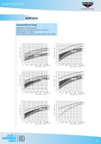
your Hydraulic Brand NOISE LEVEL Characteristics for Pumps Measured in a Sound Chamber Distance form microphone to pump = 3.3 ft (1 m) Measuring error: +2 dB (A) Fluid: Hydraulic oil to ISO VG 46 DIN 51519, t= 122°F (50°C) qvra x qzer o qvra x qzer o qvra x qzer o
Open the catalog to page 6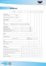
your Hydraulic Brand ORDERING CODE Axial Piston Unit Swash late variable pump Swash plate variable pump for industrial Mode of Operation Pump, open circuit Pressure control Pressure remote control Pressure and flow control Pressure & flow (w/ X port blocked) Pressure, Flow & Powe control Displacement Vgmax Control Devices Series Series Direction of Rotation Viewed from shaft end SAE-splined shaft, reinforced (higher thru drive torque) SAE-splined shaft, smaller size (not for pumps with thru drive) SAE-splined shaft, reinforced (U-type shaft) SAE-keyed shaft
Open the catalog to page 7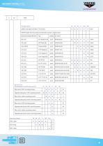
VNK0 VNK BA10VS GEAR PUMP - INTRODUCTION G0 your Hydraulic Brand Through drives Without through drive (Non- Thru Drive) With through drive to accept an axial piston pump or a gear pump Mounting flange SAEJ744 Service Ports (Pressure port B and Suction port S) Rear ports, metric mounting screws Opposite side ports, metric mounting screws Rear ports, UNC mounting screws Opposite side ports, UNC mounting screws Rear ports, UNC mounting screws ● Opposite side ports, UNC mounting screws Rear ports, metric mounting screws Opposite side ports, metric mounting screws
Open the catalog to page 8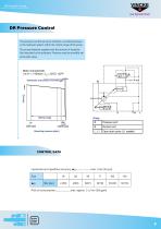
your Hydraulic Brand DR Pressure Control The pressure control serves to maintain a constant pressure in the hydraulic system within the control range of the pump. The pump therefore supplies only the amount of hydraulic fluid required by the actuators. Pressure may be smoothly set at the pilot valve. CONTROL DATA
Open the catalog to page 9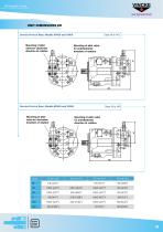
your Hydraulic Brand UNIT DIMENSIONS DR Service Ports at Rear; Models 61N00 and 11N00 Service Ports at Rear; Models 62N00 and 12N00
Open the catalog to page 10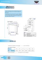
your Hydraulic Brand DRG Pressure/ Remote Control A pressure relief valve may be externally piped to port X for remote control purposes. It is not, however, included with DRG control. The differential pressure at the pilot valve is set as standard to 20 bar (290 psi) and this results in a pilot flow of (0.4gpm) 1.5 L/min. If another setting is required (in the range 10-22 bar), please state this in clear text. CONTROL DATA
Open the catalog to page 11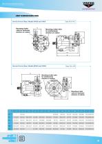
your Hydraulic Brand UNIT DIMENSIONS DRG Sizes mm(in) Service Ports at Rear; Models 61N00 and 11N00 Service Ports at Rear; Models 62N00 and 12N00
Open the catalog to page 12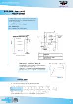
your Hydraulic Brand DFR/DFR1 Pressure/ Flow Control In addition to the pressure control function, the pump flow may be varied by means of a differential pressure at the actuator (e.g. an orifice). In model DFR1 the X orifice is plugged. Static Characteristic ( at n1 = 1450rpm ; toil = 500C) 1220F Flow Control / Diferential Pressure ∆p Standard setting: 14 bar (203psi). If a different setting is required, please state in clear text. When port X is unloaded to tank, a zero stroke pressure (“stand by”) of p = 18 +/- 2 bar (260 +/- 30 psi) results. CONTROL DATA For pressure control technical...
Open the catalog to page 13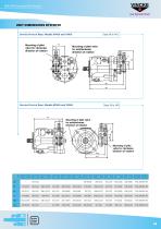
your Hydraulic Brand UNIT DIMENSIONS DFR/DFR1 Sizes mm(in) Service Ports at Rear; Models 61N00 and 11N00 Service Ports at Rear; Models 62N00 and 12N00
Open the catalog to page 14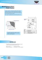
DFLR Pressure/Flow/Power Control your Hydraulic Brand DFLR Pressure/Flow/ Power Control In order to achieve a constant drive torque with a varying operating pressure, the swivel angle and with it the output flow from the axial piston unit is varied so that the product of flow and pressure remain constant. Flow control is possible below the limit of the power curve. The power characteristics is factory - set, so please enter details in clear text, e.g. 20kW at 1450 rpm (5HP, 1800RPM).
Open the catalog to page 15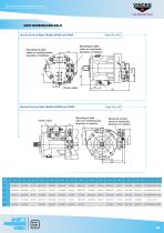
DFLR Pressure/Flow/Power Control your Hydraulic Brand UNIT DIMENSIONS DFLR Sizes mm(in) Service Ports at Rear; Models 61N00 and 11N00 Service Ports on Side; Models 62N00 and 12N00
Open the catalog to page 16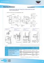
MOUNTING DIMENSIONS your Hydraulic Brand Mounting Dimensions Service Ports on Side; Non Through Drive, Models 62N00 and 12N00 without considering adjustment Shaft End K Parallel with key ISO 3019-1 19-1 2) ANSI B92.1a-1976, 30º pressure angle, flat root side fit, flank centering, tolerance class 5. Ports Designation Tightening Torque Max [lb-ft (Nm)] Pressure port (standard pressure range) Threading in bolt holes Inlet (standard pressure range) Threading in bolt holes Case drain (L1 plugged) Pilot Pressure Control pressure for DG control 1) Dependent on the installation position, port L or...
Open the catalog to page 17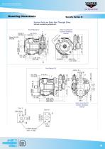
MOUNTING DIMENSIONS your Hydraulic Brand Mounting Dimensions Service Ports on Side; Non Through Drive without considering adjustment Valve mounting for counter clockwise rotation Valve mounting for counter clockwise rotation View W
Open the catalog to page 18All VINCKE HYDRAULICS catalogs and technical brochures
-
MEDIUM PRESSURE
1 Pages
-
CP16GC
3 Pages
-
K-BV HOSE BURST VALVES
1 Pages
-
VINCKE HYDRAULICS
24 Pages
-
HYDRAULICS BALL VALVES
22 Pages
-
VINCKE HYDRAULICS
71 Pages
-
VNK1-*1-1
3 Pages
-
GEARBOXES
26 Pages
-
VINCKE HYDRAULICS GEAR PUMPS
48 Pages
-
VINCKE HYDRAULICS
42 Pages
-
HYDRAULIC QUICK COUPLINGS
49 Pages
-
IN-LINE VALVES
45 Pages
-
VINCKE HYDRAULIC MOTORS
100 Pages


