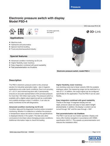
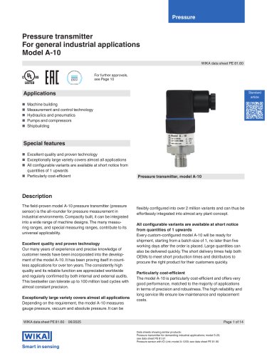
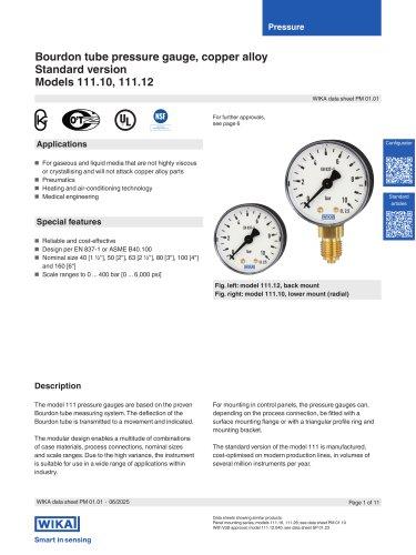
- Catalogs
- WIKA Alexander Wiegand SE & Co. KG
- Bypass level indicator With magnetic display Model BNA


Bypass level indicator With magnetic display Model BNA
Bypass level indicator With magnetic display Model BNA
Catalog excerpts
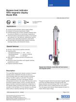
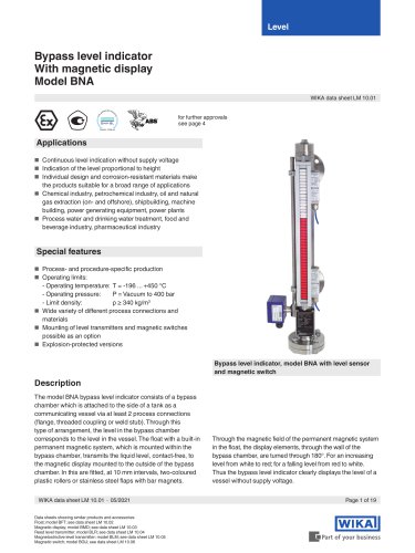
Bypass level indicator With magnetic display Model BNA WIKA data sheet LM 10.01 for further approvals see page 4 ■ Continuous level indication without supply voltage ■ Indication of the level proportional to height ■ Individual design and corrosion-resistant materials make the products suitable for a broad range of applications ■ Chemical industry, petrochemical industry, oil and natural gas extraction (on- and offshore), shipbuilding, machine building, power generating equipment, power plants ■ Process water and drinking water treatment, food and beverage industry, pharmaceutical industry Special features ■ Process- and procedure-specific production - Operating pressure: P = Vacuum to 400 bar ■ Wide variety of different process connections and materials ■ Mounting of level transmitters and magnetic switches possible as an option Bypass level indicator, model BNA with level sensor and magnetic switch The model BNA bypass level indicator consists of a bypass chamber which is attached to the side of a tank as a communicating vessel via at least 2 process connections (flange, threaded coupling or weld stub). Through this type of arrangement, the level in the bypass chamber corresponds to the level in the vessel. The float with a built-in permanent magnetic system, which is mounted within the bypass chamber, transmits the liquid level, contact-free, to the magnetic display mounted to the outside of the bypass chamber. In this are fitted, at 10 mm intervals, two-coloured plastic rollers or stainless steel flaps with bar magnets. Through the magnetic field of the permanent magnetic system in the float, the display elements, through the wall of the bypass chamber, are turned through 180°. For an increasing level from white to red; for a falling level from red to white. Thus the bypass level indicator clearly displays the level of a vessel without supply voltage. WIKA data sheet LM 10.01 • 05/2021 Page 1 of 19 Data sheets showing similar products and accessories: Float; model BFT; see data sheet LM 10.02 Magnetic display; model BMD; see data sheet LM 10.03 Reed level transmitter; model BLR; see data sheet LM 10.04 Magnetostrictive level transmitter; model BLM; see data sheet LM 10.05 Magnetic switch; model BGU; see data sheet LM 10.06
Open the catalog to page 1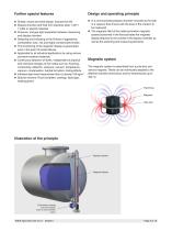
Further special features Design and operating principle ■ Simple, robust and solid design, long service life ■ In a communicating bypass chamber mounted to the side ■ Bypass chamber and float from stainless steel 1.4571, ■ Pressure- and gas-tight separation between measuring ■ Detecting and indicating of the fill level of aggressive, combustible, toxic, hot and highly contaminated media ■ The functioning of the magnetic display is guaranteed of a vessel a float moves with the level of the medium to be measured. ■ The magnetic field of the radial-symmetric magnetic system positioned in the float...
Open the catalog to page 2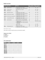
WIKA data sheet LM 1
Open the catalog to page 3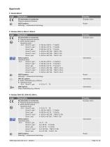
■ Models BNA-S, BNA-C, BNA-H Logo Description ■ Pressure equipment directive ■ ATEX directive (option) Hazardous areas European Union - Ex h Zone 0/1, gas 2) Zone 0/1, gas 2) Zone 2, gas Zone 0/1, dust 2) Zone 0/1, dust 2) Zone 2, dust II 1/2G Ex h IIBT6 ... T1 Ga/Gb II 1/2G Ex h IIC T6 ... T1 Ga/Gb II 3/3G Ex h IIC T6 ... T1 Gc/Gc II -/2D Ex h IIIC T68 ... T360°C -/Db II -/2D Ex h IIIC T68 ... T360°C -/Db II -/3D Ex h IIIC T80 ... T440°C -/Dc Hazardous areas - Ex h Zone 0/1, gas 2) Zone 0/1, gas 2) Zone 2, gas Zone 0/1, dust 2) Zone 0/1, dust 2) Zone 2, dust II 1/2G Ex h IIB T6 ... T1 Ga/Gb...
Open the catalog to page 4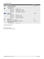
1) Only in combination with electrical components 2) With plastic cover on the display bar WIKA data sheet LM 10.01 • 05/2021
Open the catalog to page 5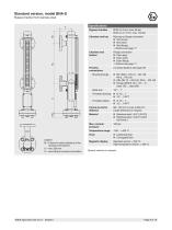
Bypass chamber from stainless steel Specifications Bypass chamber 0 60.3 x 2 mm, max. 63 bar Chamber end top Pipe cap or flange connection Chamber end bottom Process connections Mounting flange Flange connection 2 x lateral (options see page 18) ■ Flange ANSI B 16.5, 1/2" ... 4", class 150 ... class 900 Threaded bushing Threaded nipple Centre-to-centre Min. 150 mm to max. 6,000 mm distance Larger distances on request Material Legend M = Centre-to-centre distance of the process connections U = min. 200 mm X = according to process connection Max. nominal pressureTemperature range FloatMagnetic...
Open the catalog to page 6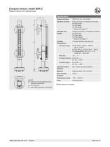
Bypass chamber from stainless steel Specifications Bypass chamber Chamber end top Chamber end bottom Process connections Mounting flange Weld stub Threaded bushing Threaded nipple Pipe cap, flange or threaded connection Flange connection or threaded connection 2 x lateral (options see page 18) ■ Flange ANSI B 16.5, 1/2" ... 2.5", class 150 ... class 300 M = Centre-to-centre distance of the process connections U = min. 150 mm X = according to process connection Material Max. nominal pressure Special versions on request WIKA data sheet LM 10.01 • 05/2021
Open the catalog to page 7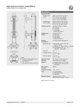
Bypass chamber from stainless steel Specifications Bypass chamber Mounting flange Weld stub Threaded bushing Threaded nipple Temperature range Float Magnetic display Pipe cap or flange connection Flange connection 2 x lateral (options see page 18) ■ Flange ANSI B 16.5, 1/2" ... 4", class 600 ... class 2,500 Min. 150 mm to max. 6,000 mm Larger distances on request Standard version: < 200 °C High-temperature version: > 200 °C Special versions on request WIKA data sheet LM 10.01 • 05/2021
Open the catalog to page 8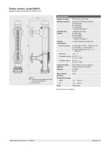
Bypass chamber and float from PVDF or PP Specifications Bypass chamber Chamber end top Chamber end bottom Process connections Mounting flange Weld stub Threaded bushing Threaded nipple Temperature range PVDF PP Float Pipe cap or threaded connection Threaded connection 2 x lateral (options see page 18) ■ Flange ANSI B 16.5, 1/2" ... 2", class 150 Min. 200 mm to max. 4,000 mm Larger distances on request Special versions on request WIKA data sheet LM 10.01 • 05/2021
Open the catalog to page 9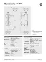
Bypass chamber from stainless steel M = Centre-to-centre distance of the process connections U = min. 150 mm X = according to process connection T = min. 100 mm Specifications Specifications Bypass chamber 0 60.3 x 2 mm, max. 63 bar Chamber end top Flange connection External sensor connection Mounting flange Female thread ANSI B 16.5, 2" class 150 ... class 600 Pipe cap or flange connection 2 x lateral (options see page 18) Mounting flange ■ DIN, DN 10 ... DN 100, PN 6 ... PN 64 ■ Flange ANSI B 16.5, 1/2" ... 4", class 150 ... class 600 Temperature range Min. 150 mm to max. 6,000 mm Larger distances...
Open the catalog to page 10