- Catalogs
- WIKA Alexander Wiegand SE & Co. KG
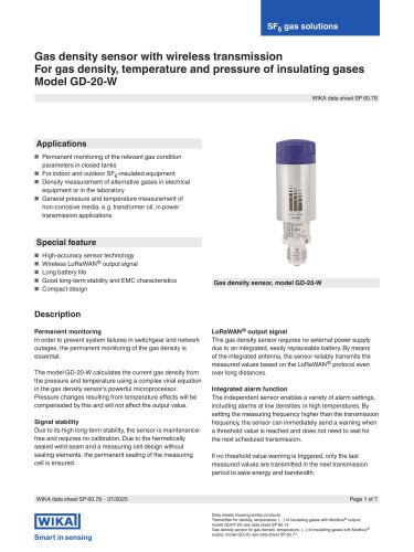
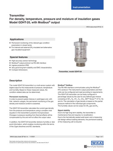
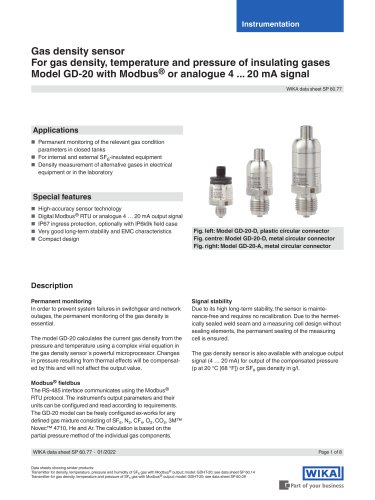
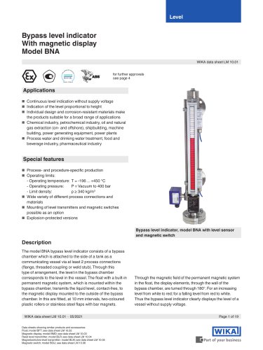
- Digital temperature transmitter For resistance sensors, head- and rail-mounted version Models T15.H, T15.R


Digital temperature transmitter For resistance sensors, head- and rail-mounted version Models T15.H, T15.R
Digital temperature transmitter For resistance sensors, head- and rail-mounted version Models T15.H, T15.R
Catalog excerpts

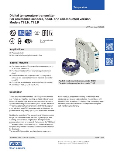
WIKA data sheet TE 15.01 Applications ■ Process industry ■ Machine building and plant construction Special features ■ For the connection of Pt100 and Pt1000 sensors in a 2-, 3- or 4-wire connection ■ For the connection of reed chains in a potentiometer circuit ■ Parameterisation with the WIKAsoft-TT configuration software and electrical connection via quick connector magWIK ■ Connection terminals also accessible from the outside Fig. left: head-mounted version, model T15.H Fig. right: rail-mounted version, model T15.R Description These temperature transmitters are designed for universal use in plant and machine building, and also in the process industry. They offer high accuracy and excellent protection against electromagnetic influences (EMI). Via the WIKAsoft-TT configuration software and the model PU-548 programming unit, the model T15 temperature transmitters can be parameterised very easily, quickly and with a clear overview. Besides the selection of the sensor type and the measuring range, the software enables the error signalling operation, damping, several measuring location descriptions and process adjustment to be stored. Furthermore, the WIKAsoft-TT software offers a line recording functionality where the temperature profile for the sensor connected to the T15 can be displayed. The model T15 transmitter also has diverse supervisory functionality, such as the monitoring of the sensor wire resistance and sensor-break detection in accordance with NAMUR NE89 as well as monitoring of the measuring range. Moreover, these transmitters have comprehensive cyclic self-monitoring functionality. WIKA data sheet TE 15.01 • 03/2025 Page 1 of 12 Temperature transmitter, model T16; see data sheet TE 16.01 Programming unit model PU-548; see data sheet AC 80.18
Open the catalog to page 1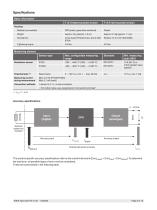
Specifications Basic information Material (non-wetted) PBT plastic, glass-fibre reinforced Cross head ('Pozidrive' tip), size 2 (ISO 8764) Tightening torque Max. configurable measuring range Measuring element Sensor type Resistance sensor Reed chains Connection methods Measuring current during measurement 10 K [50 °F] or 3.8 Ω (greater value applies) Max. 0.2 mA (Pt100/Pt1000) Max. 0.1 mA (reed) → For further notes, see „Assignment of connection terminals“ Output (analogue) Input (digital) External sensor not included Accuracy input Overall instrument accuracy Accuracy output The product-specific...
Open the catalog to page 2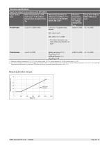
Accuracy specifications Input and output in accordance with IEC 62828 Input sensor Mean temperature coeffi- Measuring deviation at Influence Long-term drift per type cient every 10 K ambient reference conditions 1) in of auxiliary IEC 61298-2 per temperature deviation from accordance with DIN EN power every year change from ^ For further information, see chart „Measuring deviation via span" Potentiometer < ±0.01 % of MS Relative accuracy: 0.2 % ±0.005 % of MS < 0.1 % of MS 1) Reference conditions: temperature: 23 °C [73 °F] ±3 K, relative humidity: 50 -70 %, ambient pressure: 86 - 106 kPa, auxiliary...
Open the catalog to page 3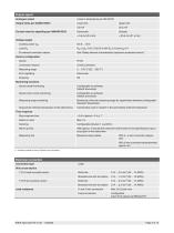
Factory configuration Monitoring functions Sensor break monitoring Time response Step response time 1) Deviation possible in case of Pt1000 4-wire connection Electrical connection WIKA data sheet TE 15.01 • 03/2025
Open the catalog to page 4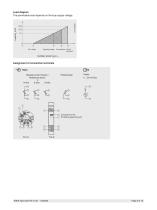
Load diagram The permissible load depends on the loop supply voltage. Operating voltage Ex equipment Non-Ex equipment Assignment of connection terminals Input Resistance thermometer / Resistance sensor in Connection of the PU-548 programming unit WIKA data sheet TE 15.01 ∙ 03/2025
Open the catalog to page 5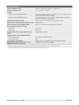
Ingress protection of the complete instrument Head-mounted version {} Items in curved brackets are options for an additional price, not for ATEX versions of the head mounting version and not for T15.R rail-mounted version 1) In the event of interference caused by high-frequency electromagnetic fields in a frequency range from 80 to 400 MHz, an increased measuring deviation of up to 0.8 % is to be expected. During transient interferences (e.g. burst, surge, ESD) take into account an increased measuring deviation of up to 1.5 %. WIKA data sheet TE 15.01 • 03/2025
Open the catalog to page 6
WIKA data sheet TE 15.01 • 03/2025
Open the catalog to page 7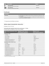
1) Internal L and C have already been considered WIKA data sheet TE 15.01 • 03/2025
Open the catalog to page 8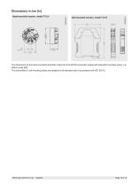
Rail-mounted version, model T15.R Head-mounted version, model T15.H The dimensions of the head-mounted transmitter match the form B DIN connection heads with extended mounting space, e.g. WIKA model BSZ. The transmitters in rail mounting cases are suitable for all standard rails in accordance with IEC 60715. WIKA data sheet TE 15.01 ∙ 03/2025
Open the catalog to page 10
Configuration Connecting the PU-548 programming unit Head-mounted version, model T15.H Rail-mounted version, model T15.R For direct communication via the serial interface of a PC/notebook, a model PU-548 programming unit is needed (see “Accessories”). Configuration software WIKAsoft-TT WIKA data sheet TE 15.01 ∙ 03/2025
Open the catalog to page 11
Accessories and spare parts Model Order number Suitable for TS 35 per DIN EN 60715 (DIN EN 50022) or TS 32 per DIN EN 50035 Material: plastic / stainless steel Dimensions: 60 x 20 x 41.6 mm Suitable for TS 35 per DIN EN 60715 (DIN EN 50022) Material: steel, tin-plated Dimensions: 49 x 8 x 14 mm Magnetic quick connector, model magWIK Replacement for crocodile clips and HART® terminals Fast, safe and secure electrical connection For all configuration and calibration processes Programming unit model PU548 Programming unit for USB interface for use with the WIKAsoft-TT configuration software Easy...
Open the catalog to page 12