
MW
MW
Catalog excerpts
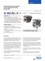
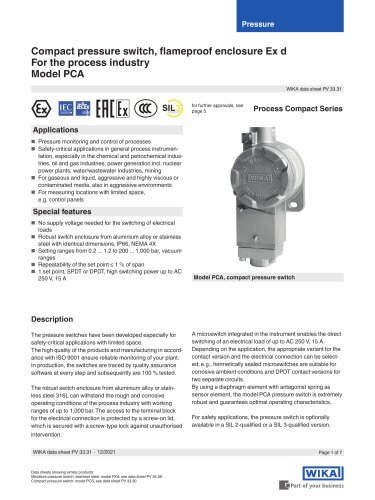
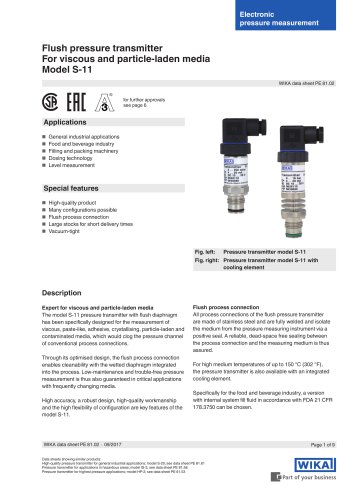
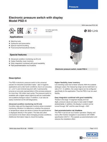
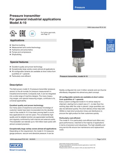
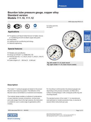
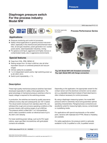
Diaphragm pressure switch For the process industry Model MW WIKA data sheet PV 31.10 for further approvals, see page 6 Process Performance Series ■ Pressure monitoring and control of processes ■ Safety-critical applications in general process instrumen- tation, especially in the chemical and petrochemical industries, oil and gas industries, power generation incl. nuclear power plants, water/wastewater industries, mining ■ For gaseous and liquid, aggressive and highly viscous or contaminated media, also in aggressive environments Special features ■ Case from 316L, IP66, NEMA 4X ■ Setting ranges from 16 mbar to 600 bar, also all other equivalent vacuum or combined pressure and vacuum ranges ■ Intrinsic safety Ex ia available ■ 1 or 2 independent switch points, high switching power up to AC 250 V, 20 A ■ Switch point repeatability < 1 % Fig. left: Model MW with threaded connection Fig. right: Model MW with flange connection Description These high-quality mechanical pressure switches have been developed especially for safety-critical applications. The great advantage of mechanical pressure switches is that no supply voltage is required for the switching process. Depending on the application, the appropriate variant for the contact version and the electrical connection can be selected; e.g. adjustable dead band instead of fixed dead band is often a feature necessary for control processes. In production, the switches are traced by quality assurance software at every step and subsequently are 100 % tested. The robust switch enclosure from stainless steel 316L can withstand the rough and corrosive operating conditions of the process industry with working ranges of up to 600 bar. The pressure switch is fitted with 1 or 2 microswitches, which make it possible to switch an electrical load of up to AC 250 V, 20 A directly. By using a diaphragm measuring system, the model MW pressure switch is extremely robust and guarantees optimal operating characteristics. Flanged process connections are excellently suited for measuring highly viscous, contaminated or crystallising media. For lower switching power ratings, such as for PLC applications, argon gas-filled microswitches with gold-plated contacts are available. WIKA data sheet PV 31.10 ∙ 04/2022 Data sheets showing similar products: Diaphragm pressure switch, flameproof enclosure Ex d; model MA; see data sheet PV 31.11 For applications with special requirements on the wetted parts, versions with materials from PTFE, Monel or Hastelloy are available. For safety applications, the pressure switch is optionally available in a SIL 2-qualified or a SIL 3-qualified versio
Open the catalog to page 1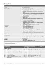
Basic information Version Special design feature Contact version Diaphragm pressure switch ■ Version for hazardous areas (Ex ia) ■ Per NACE 1) MR0175 / ISO 15156, use in H2S-containing environments in oil and gas production ■ Per NACE 1) MR0103 / ISO 17945, metals resistant to sulphide stress cracking ■ Version compliant with EN 1854, pressure sensing devices for gas burners and gas burning appliances ■ Version compliant with EN 12952 and EN 12953, limiting devices in water-tube and shell boilers ■ Drying of wetted parts ■ Tropical version (suitable for environments with increased air humidity)...
Open the catalog to page 2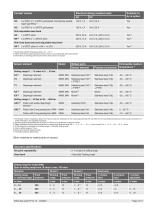
WIKA data sheet PV 31.10 • 04/2022
Open the catalog to page 3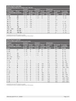
1) Diaphragm element with PTFE coating is not available 2) Proof pressure of 100 bar not available for wetted parts from PTFE and Monel Setting range for model MW Span of setting range from 0.2 bar to max. 40 bar 1) Diaphragm element with PTFE coating is not available 2) Proof pressure of 100 bar not available for wetted parts from PTFE and Monel WIKA data sheet PV 31.10 • 04/2022
Open the catalog to page 4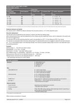
1) Only available for models MWB and MW Other process connections on request WIKA data sheet PV 31
Open the catalog to page 5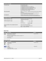
Electrical connection WIKA data sheet PV 31.10
Open the catalog to page 6
WIKA data sheet PV 31.10 • 04/2022
Open the catalog to page 7
Dimensions in mm [in] Model MWB Span of setting range from 16 mbar to max. 100 mbar Electrical connection Process connection Models MW, MWG, MWH Span of setting range from 0.2 bar to max. 600 bar Sensor element: Piston with welded diaphragm Sensor element: Piston Sensor element: Diaphragm Electrical connection Process connection Permissible mounting positions With affixed lead seal Vertical Position not possible for span of setting range from 16 mbar to 100 mbar WIKA data sheet PV 31.10 ∙ 04/2022
Open the catalog to page 8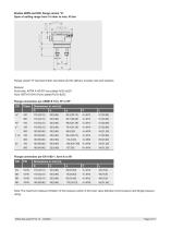
Flange variant “S” has fixed metric stud bolts and the delivery includes nuts and washers. MaterialStud bolts: ASTM A193-B7 zinc-plated Fe/Zn 8c2C Nuts: ASTM A194-2H zinc-plated Fe/Zn 8c2CFlange connection per ASME B 16.5, FF or RF 150 300 150 150 300 Note: The maximum pressure limitation of the pressure switch is the lower value between proof pressure and flange pressure rating. Page 9 of 11 WIKA data sheet PV 31.10 • 04/2022
Open the catalog to page 9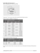
Models MWB and MW, flange variant “T” Span of setting range from 16 mbar to max. 40 bar Flange variant “T” has an extension pipe to alllow mounting the standard flange connections. Flange connection per ASME B 16.5, FF, RF or RJ Flange connection per EN 1092-1, form A or B1 Note: The maximum pressure limitation of the pressure switch is the lower value between proof pressure and flange pressure rating. Page 10 of 11 WIKA data sheet PV 31.10 • 04/2022
Open the catalog to page 10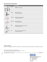
Accessories and spare parts Model Syphons → See data sheet AC 09.06 Overpressure protector → See data sheet AC 09.04 Needle valve and multiport valve → See data sheet AC 09.22 Block-and-bleed valve → See data sheet AC 09.19 Monoflange, process and instrument version → See data sheet AC 09.17 Ball valve, process and instrument version → See data sheet AC 09.28 Ordering information Model / Unit / Setting range of set point / Contact version / Process connection / Electrical connection / Wetted parts / Options © 12/2010 WIKA Alexander Wiegand SE & Co. KG, all rights reserved. The specifications...
Open the catalog to page 11