
- Catalogs
- Winterwarm Heating Solutions BV
- AIR HEATER TYPE DXC


AIR HEATER TYPE DXC

AIR HEATER TYPE DXC
This manual is intended for gas, electrical, and mechanical installers, providing comprehensive instructions for the safe use and maintenance of the DXC air heater. It highlights the importance of following guidelines to ensure safe operation and maintain warranty validity.
- Installation: Must be conducted by qualified personnel using calibrated equipment, in compliance with local regulations.
- Use: Keep the area around the heater dry during maintenance, and ensure doors and hatches are closed unless adjustments are necessary.
- Maintenance & Cleaning: Regular maintenance is essential, particularly in dusty or wet environments. Avoid using water on electrical components.
- Children and Vulnerable Users: Supervision is required for children and vulnerable individuals using the heater.
- Performance: Includes details on heat input, output, efficiency, and air output for models DXC60, DXC80, and DXC100.
- Gas Types: Compatible with natural gas, propane, and butane/LPG, with specific consumption and pressure details.
- Dimensions: Provided in a diagram for installation reference.
- Preparation: Verify heater specifications against local provisions before installation.
- Positioning: Maintain safe distances from flammable materials and ensure unobstructed airflow.
- Gas Connection: Ensure correct gas type and pressure, with a manual isolation valve within reach.
- Electrical Connection: Requires a 230 V/AC power supply, with specific wiring instructions provided.
- Room Thermostat: Guidelines for optimal thermostat placement and connection.
Instructions on flue terminal installation, maximum flue length, and condensate management.
Details on manual function switches, burner cycles, and safety features like overheating protection.
Guidance on adjusting burner settings and converting to different gas types.
Common issues, error codes, and solutions for volatile lockouts and temporary errors.
Regular and extensive maintenance procedures, especially for units in poultry sheds.
Includes electrical wiring diagrams, exploded views for spare parts, and a declaration of conformity.
This document provides detailed instructions for the installation and operation of the Air Heater Type DXC. It includes specifications for setting switches, connecting thermostats, and installing flue systems, as well as guidelines for operating the heater and ensuring safety.
Each air heater in a system must have a unique J14 switch setting to function correctly. The heater must be turned off when adjusting these switches to ensure the settings take effect.
To connect an ON/OFF room thermostat, connect the thermostat wires to terminals 6 and 7. Ensure these connections are not combined with other heaters and use separate relays for each heater.
The air heater must be connected to a flue system that complies with national and local regulations. The document specifies compatible flue terminals and materials, such as CE marked flue materials from Muelink & Grol and Burgerhout. The maximum flue length is 9 meters for vertical and 6 meters for horizontal installations, with adjustments for bends.
Condensate formation is more likely in smaller heaters and can be managed by adding a T-piece or condensate drain. Insulating flue pipes or using a condensate trap is recommended for longer flue pipes.
Instructions are provided for installing flue terminals through roofs or walls, emphasizing compliance with regulations and avoiding mixing components from different manufacturers.
The air heater can be controlled manually with a function switch, offering modes such as standby, continuous fan operation, and continuous burning. The burner cycle is displayed on the heater, indicating various operational stages.
The heater includes overheating protection with an NTC sensor and a pressure switch to ensure proper combustion air passage. The heater will attempt to ignite twice before displaying an error if unsuccessful.
Commissioning involves ensuring the gas supply is clean and observing the first start-up. Adjustments should only be made with calibrated instruments and a supporting flue gas analysis. The document stresses the importance of instructing the end user on safe operation and maintenance.
- Initial adjustments of the air heater control are not necessary immediately after commissioning. Adjustments should be made by qualified personnel using calibrated equipment to prevent overheating and carbon monoxide production.
- Burner settings involve adjusting high and low burner pressures using a gas valve. Specific steps and tools required for these adjustments are outlined.
- Conversion should only be performed by the manufacturer or a qualified technician. It involves changing gas injectors and requires a conversion kit.
- Detailed steps for conversion include shutting off gas and electricity, replacing injectors, and ensuring proper sealing and labeling for the new gas type.
- Includes tables of volatile lockouts, temporary errors, and warnings with corresponding error codes and descriptions.
- Specific cases are provided for common issues such as ignition errors, overheating, sensor failures, and configuration errors, along with potential solutions.
- Annual inspection and cleaning by a qualified installer are required, with special attention to high humidity and dusty environments.
- Basic maintenance involves cleaning various parts of the heater, checking wiring and connections, and ensuring no gas leaks.
- Extensive maintenance is required for heaters used in poultry sheds, including cleaning with compressed air and ensuring the motor is free of dust.
- Includes a complete electrical wiring diagram and highlights key connections necessary for installation.
- Adjustments and conversions should only be performed by qualified personnel to prevent safety hazards.
- Regular maintenance is crucial to ensure the safe and efficient operation of the air heater.
This document is an installation manual for the Air Heater Type DXC, covering models DXC60, DXC80, and DXC100. It includes detailed specifications, installation procedures, and compliance information.
The manual provides an exploded view of the air heater, listing parts such as the burner, ignition electrode, combustion fan, gas valve, system fan, and more. Each part is associated with a specific article number for replacement purposes.
- Burner: IB3204
- Ignition Electrode: GA3400
- Combustion Fan: GA4516/GA4517
- Gas Valve: GA3314
- System Fan: IP4811/IP4801/IP4813
- Burner Control Unit: GY5901
- Pressure Switch: IB3904/IB3911
- Heat Exchange Sensor: GY3935
The air heaters comply with several EU directives, ensuring safety and compatibility:
- 2016/426/EU (GAR) for gaseous fuel appliances
- 2014/35/EU (LVD) for electrical safety
- 2014/30/EU (EMC) for electromagnetic compatibility
- 2006/42/EG (MD) for machinery safety
Issued by Winterwarm Heating Solutions B.V., the declaration confirms that the air heaters meet essential EU requirements. The document is signed by Ir. M. Fiselier, Manager of Research and Development, dated July 1st, 2019.
Catalog excerpts

INSTALLATION MANUAL AIR HEATER TYPE DXC C€
Open the catalog to page 1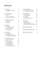
1.1 Symbols used in this manual 3 2.4 Children and vulnerable users 4 5.3 Condensate in the flue system 13 5.4 Installation of the flue terminal 14 6.1 Manual function switch 16 6.2 Minimum firing time 17 6.5 Flue passage check 17 8.1 Adjusting the burner settings 19 8.2 Converting to another gas type 19 9.1 Volatile lock outs 20 10.3 Maintenance of the burner unit 23 10.4 Extensive maintenance in poultry sheds 24 11 Electrical wiring diagram 25 12 Exploded view and spare parts 26
Open the catalog to page 2
1 Introduction This manual is intended for the gas, electrical and mechanical installer. This document gives instructions on how to use and maintain the air heater. It is most important to follow the instructions in this document for safe operation of this air heater. It is important to read this document before starting the installation process. Store this document close to the air heater for quick reference. 1.1 Symbols used in this manual DANGER! Indicates a dangerous situation that would lead to death or severe injury. WARNING! Indicates a potentially dangerous situation that could lead to...
Open the catalog to page 3
2 Safety instructions Always follow the safety instructions in this chapter when installing, using or performing maintenance on this air heater: CAUTION! Always close the doors and inspection hatches of the air heater, except when adjusting and checking the appliance. CAUTION! This air heater must be installed and maintained by an authorized, qualified and competent installer, using calibrated equipment. Frequent maintenance and cleaning of the air heater is necessary to ensure safe and proper operation. Failure to do so could lead to damage to the heater or its surroundings and void the warranty....
Open the catalog to page 4
4 Installation 4.1 Preparation Before installation, please use the data badge to check: • if the heater is in accordance with the order; • if the heater is suitable for the local present provisions (gas type, gas pressure, electrical supply etc.) • Make sure enough space remains to open the door of the air heater. • Make sure the wall can support the air heater. • Ensure sufficient clearance distance for the flue system. Before leaving the factory, the air heater has been tested for safety and has been set to the operating settings. It has been configured for the type of gas that is stated on...
Open the catalog to page 8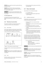
NOTICE All gas supply lines must be mounted without any mechanical tension. NOTICE Always clean the inside of a gas supply line before connecting it to the air heater. Place a gas filter in the supply line when needed. • When replacing this fuse, always use one of the same type (5AT). 4.5 Room thermostat The air heater can be controlled in two ways: CAUTION! When using pressures above 60 mbar to test the supply lines, always close the manual isolation valve of the air heater. • by an ON/OFF signal; • through a bus communication system with an external interface. For United Kingdom only: The supply...
Open the catalog to page 9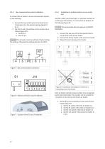
To connect the air heater to a bus communication system, do the following: 1. Connect the two control wires to terminals 4 and 5 (see figure 5 or the electrical wiring diagram in §11). 2. Set the S1 and J14 switches on the control unit as follows (figure 6/7): ||The air heater must be switched off when setting the switches. Otherwise the settings will have no effect. An MTC or MTS room thermostat, or interface module can control up to 8 air heaters. To connect the air heaters, do the following (figure 8): ||This functionality does not apply to an ON/OFF thermostat. 1. Connect the two wires of...
Open the catalog to page 10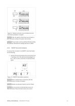
Figure 9 - Positions of the S1 and J14 switches for the first three air heaters in a system NOTICE If the J14 switch of more than one air heater is set to the same number, the system will not work. NOTICE The air heater must be switched off when setting the switches. Otherwise the settings will have no effect. ON/OFF thermostat installation To connect the air heater to an ON/OFF room thermostat, do the following: • Connect the two thermostat wires to terminal 6 and 7 (see figure 10 or the electrical wiring diagram in §11). This is a 24 V connection for the thermostat signal. Figure 10 - ON/OFF...
Open the catalog to page 11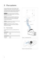
To ensure safe and proper use, this air heater must be connected to a flue system. This flue system must be installed according to this manual as well as national and local regulations. A flue system consists of a flue terminal, piping and an optional condensate discharge system. Do not use flue terminals for condensing appliances on non-condensing heaters. This can lead to water inside the flue system. NOTICE [lOnly use the prescribed flue material for the roof terminal, wall terminal and for the piping between the heater and the terminal. This is the only way the installation will be approved....
Open the catalog to page 12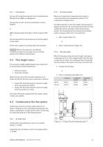
5.1.1 Flue material Only use CE marked flue material from the manufacturers Muelink & Grol (M&G) and Burgerhout. Use type Alu-fix with a minimum temperature class of T200 P1. or M&G's Stainless Steel SP Isoflex 0.10 flue material T200 P1. Use flue pipes with the same diameter as the flue spigots on the heater. 5.3.2 Air heater location When an air heater burns frequently and is placed in a normally heated room (temperature above 15 °C), condensate is unlikely to form. Air heaters placed in a room that needs to be just above 5 degrees will only burn for short periods at the time. Formed condensate...
Open the catalog to page 13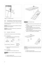
Figure 14 - Condensate drain 5.4 Installation of the flue terminal NOTICE There are flue terminals available for installation through a roof or through a wall. ||The flue terminal must be installed according to local and national regulations. Do not combine components or materials from different manufacturers. 4. Put the flue terminal into a vertical position. Use a level. 5. OPTIONAL - If desired, fit cover plates. These are supplied separately. 6. Place the supplied wall clamp around the flue terminal and fit it to the roof construction. Do not tighten the clamp yet. 7. Connect the gasket and...
Open the catalog to page 14All Winterwarm Heating Solutions BV catalogs and technical brochures
 Winterwarm XR+ series
4 Pages
 AIR HEATER TYPE DXE
24 Pages
 AIR HEATER TYPE DXA
24 Pages
 Winterwarm Agri 2018
16 Pages
 Winterwarm WWH Series
4 Pages
 Winterwarm WCU
4 Pages
 Winterwarm TRD
4 Pages
 Winterwarm XR Series
4 Pages
 Winterwarm HR-series
4 Pages
 Agri Export catalogue
16 Pages
 Product- and Price catalogue
44 Pages
 Agri brochure
16 Pages
Archived catalogs
 Winerwarm Agri 2013
12 Pages