WC68

WC68
The WC68 PTO Wood Chipper is intended for acreage owners to chip natural, untreated wood. Adhering to the manual for assembly, operation, and maintenance is crucial for safety and optimal performance.
The chipper requires a minimum of 20 HP at the PTO, features a 24-inch flywheel, and weighs 710 lbs. It includes a hydraulic in-feed system that does not need external hydraulic connections.
Important safety measures include thoroughly reading the manual, operating the machine solo, wearing appropriate safety gear, and avoiding loose clothing or jewelry. The chipper should not be used near bystanders or on public roads.
The chipper is delivered in a steel crate and requires minimal assembly. Key steps include assembling the infeed chute panels, attaching the infeed roller control handle, and ensuring all hardware is securely tightened. The hydraulic oil tank must be filled with 20 liters of ISO 32 hydraulic oil before use.
Before starting, ensure the chipper is properly attached to the tractor and the PTO shaft is connected. The discharge chute can be adjusted for chip ejection direction and distance. Begin with smaller branches to familiarize yourself with the machine.
Regular maintenance involves replacing and sharpening blades, adjusting the hydraulic pump belt tension, and greasing all bearings. Blades are reversible and should be maintained to ensure efficiency.
Blades should be sharpened every 25-50 hours of operation. The WC68 uses four reversible hardened steel blades. Steps include disconnecting the PTO shaft, opening the flywheel housing, removing the blades, grinding at a 33-degree angle, and reinstalling with new hardware torqued to 40-45 ft-lbs.
The gap between the bed plate and chipping blades should be set to 1/16”-1/8”. This involves disconnecting the PTO shaft, accessing the blades, aligning the bed plate, and securing it with M10 bolts tightened to 40 ft-lbs.
Check the belt every 30 hours. It should be under firm tension. Adjust by tightening the eye bolt attached to the spring.
If the belt is worn or slipping, replace it by disconnecting the PTO shaft, loosening the eye bolt, removing the old belt, and installing a new one with proper tension.
The chipper has five grease zerk fittings. Grease should be added as needed to the PTO shaft, flywheel shaft, and infeed roller bearings.
A detailed list of parts with descriptions and quantities is provided, including various bolts, washers, and components like the hydraulic tank, infeed roller, and flywheel.
Catalog excerpts

Owner’s Manual
Open the catalog to page 1
UNPACKING6 INFEED CHUTE PANELS6 INFEED ROLLER CONTROL HANDLE9 INFFFD ROI I FR I INKAGF ARM9 DISCHARGE CHUTF10 HARDWARE10 HYDRAULIC OIL10 PTO SHAFT LENGTH11 OPERATION 12 START UP12 DISCHARGE CHUTE ADJUSTMENT12 DISCHARGE CHUTE DEFLECTOR13 CHIPPING13 STOPPING14 INFFFD RO! ! FR CONTRO!15 MAINTENANCE & SERVICE 16 REPLACING BLADES16 SHARPENING BLADES17 SETTING BED PLATE GAP18 ADJUSTING HYDRAU IC PUMP BEL T TFNSION20 RFPj ACING HYDRAU IC PUMP BEL T21 GREASABLE BEARINGS21 PARTS LIST 22
Open the catalog to page 2
Dear Woodland Mills Customer, Congratulations and thank you for choosing the Woodland MillsTM WC68 wood chipper! It was designed to be the best valued PTO wood chipper on the market. Please take the time to read through the manual for detailed instructions on assembly, operation and maintenance. Following the procedures and recommendations in this manual will ensure you yield maximum performance and safety from the WC68 wood chipper. For any technical questions or replacement parts, please contact Woodland MillsTM at 1-855-476-6455 OWNER'S RECORD Please take a moment to record the following information...
Open the catalog to page 3
INTENDED USE Woodland Mills chippers are designed for acreage owners to aid in chipping natural, untreated wood only. Materials that are processed may contain chemicals or by-products that could corrode the machine or damage it, resulting in safety concerns. SPECIFICATIONS
Open the catalog to page 4
SAFETY • Do not operate this machine until this manual has been read and fully understood; serious injury or severe machine damage can occur if these safety warnings are ignored. • Never allow more than one person to operate this machine at one time. If two people are working together it will increase the chance of your workmate engaging the machine or causing you to fall into the machine. • If your hand is ever near the chipping or feeding area serious injury can occur. • Never place your hands or feet on or near the machine while it is engaged. • Never place your hands or feet on or near the...
Open the catalog to page 5
STAY CLEAR OF ROTATING DRIVELINES • Entanglement in rotating driveline can cause serious injury or death. • Keep tractor master shield and driveline shields in place at all times. Make sure rotating shields turn freely. • Wear close fitting clothing. • Stop the engine and be sure that PTO driveline is stopped before making adjustments, connections, or cleaning out PTO driven equipment. • Do not install any adapter device between the tractor and the primary implement PTO drive shaft that will allow a 1000 rpm tractor shaft to power a 540 rpm implement at speeds higher than 540 rpm. • Do not install...
Open the catalog to page 6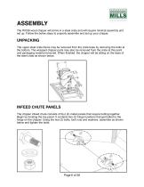
ASSEMBLY The WC68 wood chipper will arrive in a steel crate and will require minimal assembly and set up. Follow the below steps to properly assemble and set up your chipper. UNPACKING The upper steel crate frame may be removed from the crate base by removing the bolts at the bottom. The wrapped chipper parts may also be removed from the crate at this point and packaging material removed. When finished, the chipper will be sitting on the base of the steel crate as shown below. INFEED CHUTE PANELS The chipper infeed chute consists of four (4) metal panels that require bolting together. Begin by...
Open the catalog to page 7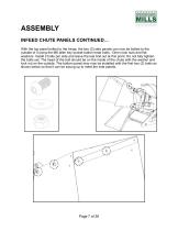
ASSEMBLY INFEED CHUTE PANELS CONTINUED… With the top panel bolted to the hinge, the two (2) side panels can now be bolted to the outside of it using the M6 allen key socket button head bolts, 13mm lock nuts and flat washers. Install 2 bolts per side and leave the last bolt out at this point. Do not fully tighten the bolts yet. The head of the bolt should be on the inside of the chute with the washer and lock nut on the outside. The bottom panel may now be installed with the first two (2) bolts as shown below so that it can be swung up to meet the side panels.
Open the catalog to page 8
ASSEMBLY INFEED CHUTE PANELS CONTINUED… The round edge bar is designed to add additional strength to the infeed panels and also act as a rounded edge, eliminating branches from getting caught on the edge of the infeed panels. To install it, swing the bottom panel up as shown below and fit the tabs of the round bar on the outside of the panels. and are held in place using five (5) M6 allen key headed bolts, 13mm lock nuts and flat washers. There are two tabs on the side of the round edge bar which will be bolted to the side panels in the following step. The remaining bolts can be installed as...
Open the catalog to page 9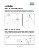
ASSEMBLY INFEED ROLLER CONTROL HANDLE The large red coloured infeed control handle is attached using the two (2) M10 allen key headed bolts, lock nuts and flat washers. These bolts will go through the panel, round edge bar side tabs and through the control handle as shown below. With all of the bolts loosely installed for the infeed panels, they can all be tightened securely. INFEED ROLLER LINKAGE ARM With the control handle now fastened to the infeed chute, the linkage arm can be connected to it and the hydraulic control valve as shown below. The M10 bolt and nut is used to fasten the heim joint...
Open the catalog to page 10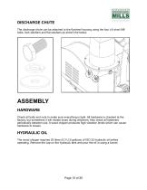
DISCHARGE CHUTE The discharge chute can be attached to the flywheel housing using the four (4) short M8 bolts, lock washers and flat washers as shown the below. ASSEMBLY HARDWARE Check all bolts and nuts to make sure everything is tight. All hardware is checked at the factory, but sometimes it will vibrate loose during shipment. Also check all fasteners periodically between use. A wood chipper produces high vibration levels which can cause hardware to loosen. HYDRAULIC OIL The wood chipper requires 20 litres (5.3 U.S gallons) of ISO 32 hydraulic oil before operating. Remove the cap on the hydraulic...
Open the catalog to page 11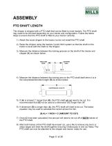
ASSEMBLY PTO SHAFT LENGTH The chipper is shipped with a PTO shaft that can be fitted to most tractors. The PTO shaft may need to be trimmed depending on your tractor and configuration. Follow the below steps to ensure that the PTO shaft is fitted to your tractor correctly. 1) Attach the wood chipper to the tractor, but do not install the PTO shaft. 2) Raise the chipper using the tractors 3 point hitch system so that the shaft on the tractor is level with the shaft on the chipper. 3) Measure the distance between the locking grooves on the shaft of the tractor and chipper (A) as shown below. !...
Open the catalog to page 12All Woodland Mills Europe AB catalogs and technical brochures
 DISCOVER THE WOODLAND™
52 Pages
 FP1413
19 Pages
 HM130
HM13056 Pages
 HM126 Sawmill
43 Pages
 HM122
HM12251 Pages
- Sawmill
- PTO-driven wood shredder
- Mounted wood shredder
- Hydraulic supply wood shredder
- Firewood processor
- Stump grinder
- Electric sawmill
- Firewood processor with belt conveyor
- Firewood processor with chainsaw
- Portable sawmill
- Mounted stump grinder
- PTO-driven stump grinder
- Gasoline engine sawmill
- Gasoline engine firewood processor
- Towed firewood processor